32
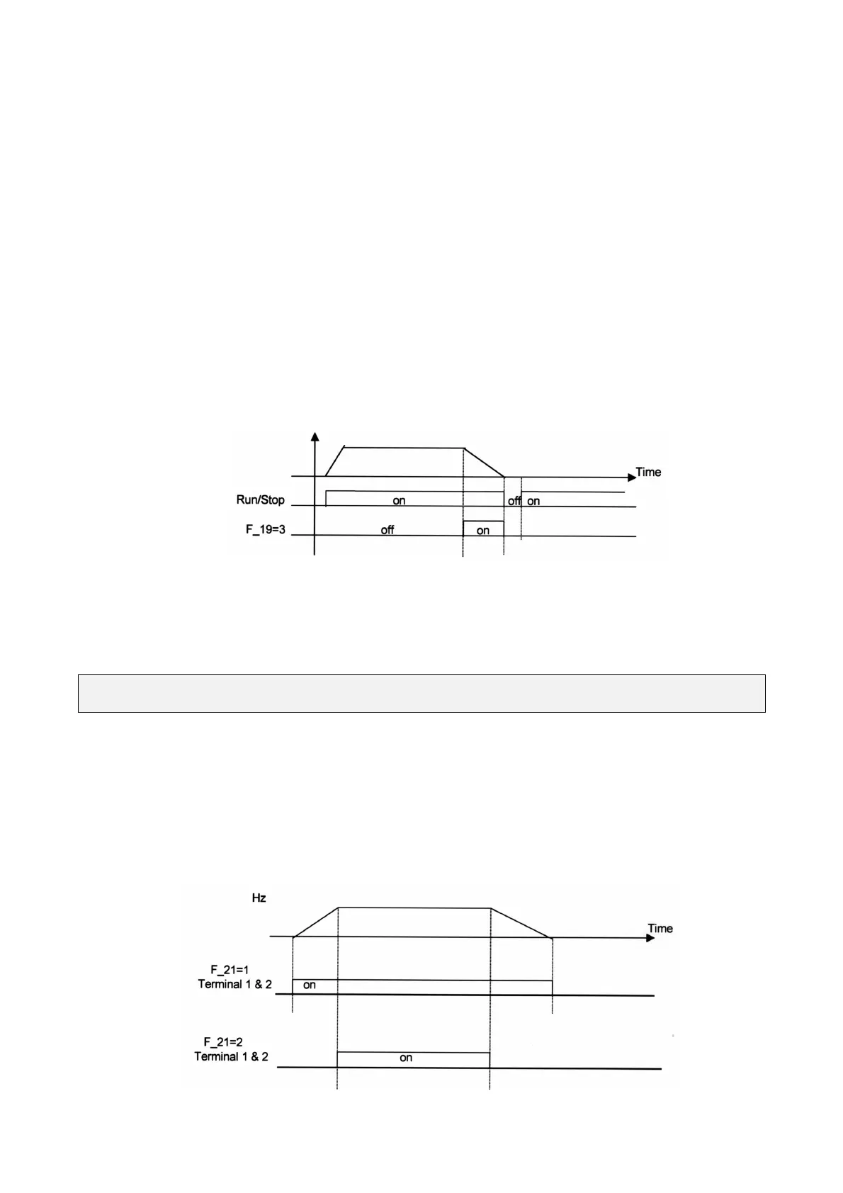
3. Fn_19, Fn_20 =3: External emergency stop signal
When the external emergency stop signal is activated, the inverter proceeds to decelerate and
stop, (ignoring the setting of Fn_14). The inverters E.S. light will flash after stopping. After the
emergency stop signal is deactivated, turn the RUN switch OFF and then ON again to cycle it.
(Fn_10 =1) Or, push the RUN key (Fn_10=0). The inverter will then resume operation and restart.
If the emergency stop signal is removed before the inverter stops, the inverter will still execute the
emergency stop.
4. Fn_19, Fn_20 =4: External Base Block (immediate shut off)
When the external base block signal is activated, the inverter output will be immediately shut off
(ignoring setting in Fn_14) and flash b.b. After the base block signal deactivated, turn the RUN
switch OFF and then ON again (Fn_10 = 1) or push the RUN key (Fn_10=0), the inverter will
restart from the starting frequency.
5. Fn_19, Fn_20 = 5: Reset when inverter fault.
Fn_21: Multi-function output terminal = 1 up to 3
1.
Fn_21 = 1: Run mode signal
2. Fn_22 = 2: Frequency agreed signal
3. Fn_21 = 3: Fault signal
Terminal 1 and 2 of TM2 are activated at CPF, OL1, OL2, OCS, OCA, OCC, Ocd , Ocb , OVC , LVC ,
OHC.