7
Accessories for Drawout Breakers
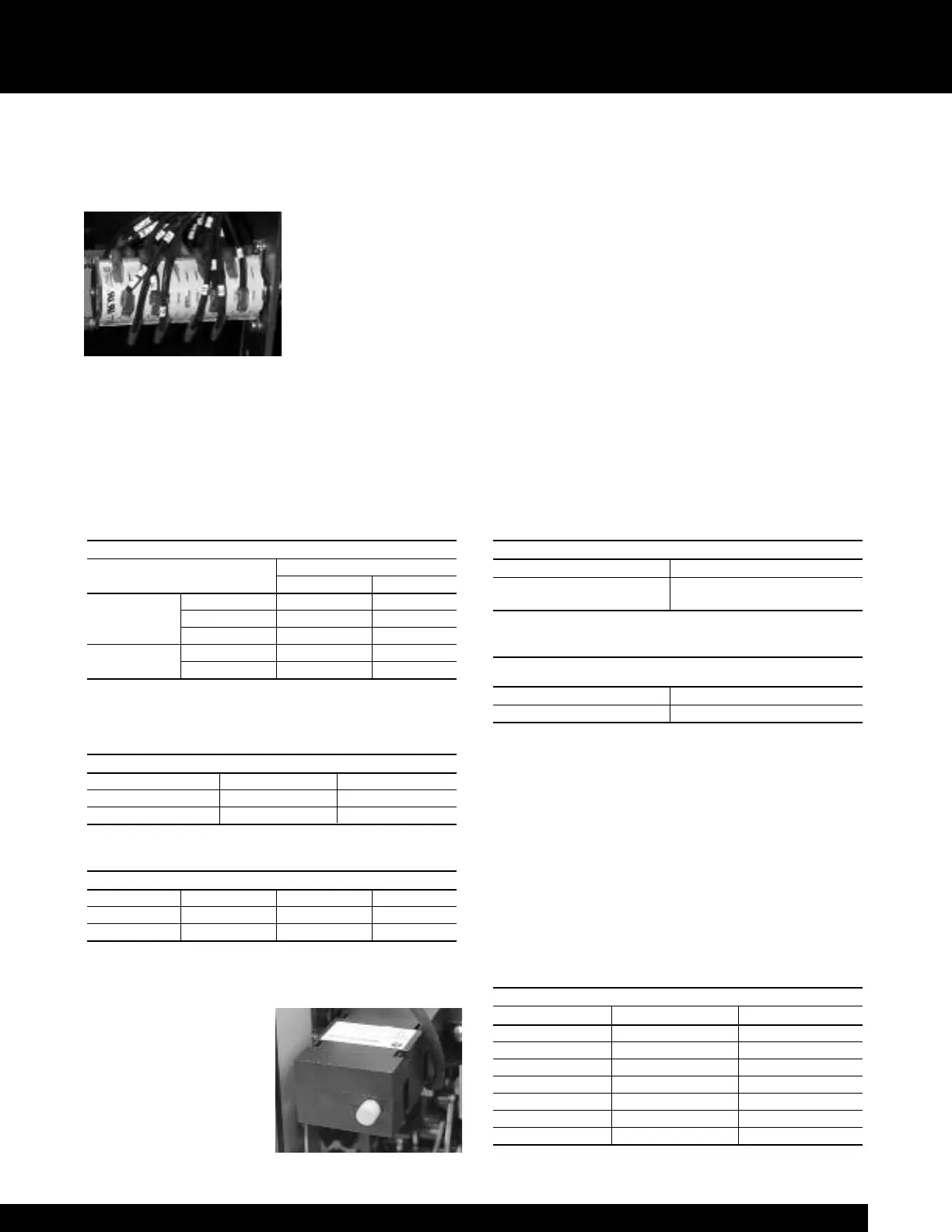
Auxiliary Switch (Field installable kit available)
The auxiliary switch is used for indication of breaker main
contact position. It is available on manually and electrically
operated breakers in either
a 4-stage or 7-stage config-
uration. The 4-stage switch
yields 3NO and 3NC con-
tacts while the 7-stage
switch yields 6NO and 6NC
contacts. Normally open
(NO) contacts follow the
breaker primary contact position while normally closed
(NC) contacts operate opposite the breaker primary con-
tacts. All auxiliary switch contacts feature rugged double-
break construction. Refer to breaker wiring diagram
10057403P1 for contact configurations and secondary dis-
connect terminations. Ratings of the auxiliary switch con-
tacts are shown in Table 7.1.
Table 7.1 Auxiliary switch ratings and contact operation
Table 7.2
Table 7.3
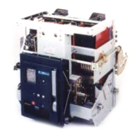
Bell Alarm with/without Lockout (Field installable kit available)
The bell alarm device is provided with two C-form contacts
— each C-form contact is
1NO and 1NC contact with
a common connection. The
bell alarm device operates
whenever the breaker trips
due to a protective function
of the trip unit. It can be
used to provide remote indi-
Field installable auxiliary switch kit catalog numbers
Auxiliary switch WP-08 / 16 / 20 WP-32 / 40 WP-50
Four stage WPAUXSF4STG WPAUXLF4STG WPAUXXF4STG
Seven stage WPAUXSF7STG WPAUXLF7STG WPAUXXF7STG
Auxiliary switch contact operation
Breaker primary contacts “a”-contact (NO) “b”-contact (NC)
Open or tripped Open Closed
Closed Closed Open
Auxiliary Switch Ratings ①
Rating (Amperes)
Control Voltage Non-inductive Inductive
24 15 10
DC 125 10 5
250 5 5
AC - 60Hz
120 15 15
240 10 10
① 20A continuous rating of switch limited to 15A continuous
rating of #16AWG wire on drawout breakers
cation of a fault trip and/or disable electrical operation of
breakers that may have automatic control.
For Power+™ and MicroVersaTrip Plus™ trip units, the bell
alarm will operate for overload, short circuit and ground
fault trips. For MicroVersaTrip PM™ trip units, the bell
alarm will operate for the same overcurrent trips plus any
of the
protective relay trips that are enabled in the trip unit.
Tripping via the manual trip button, shunt trip, undervoltage
device or open fuse lockout will not operate the bell alarm.
The bell alarm can be furnished with a mechanical lockout
feature that will prevent the breaker from being manually
closed until the lockout is reset. Reset of the contacts and lock-
out feature is accomplished by pushing the yellow “reset” but-
ton on the breaker escutcheon. The reset button also serves as
a target indicator that the bell alarm has been operated.
Ratings of the bell alarm contacts are shown in Table 7.4.
Table 7.4 Bell alarm contact ratings
Table 7.5
Electrical Lockout (Field installable kit available)
The electrical lockout device provides a means to electrically
enable or disable manual closing of a circuit breaker. This
device must be energized prior to attempting to manually
close the breaker. Once the breaker is closed, loss of voltage
will not trip the breaker. A manual bypass interlock is pro-
vided for initial startup. Refer to the undervoltage device for
ratings and coil characteristics. (Note: Interlocking of elec-
trically operated breakers does not require an electrical
lockout device.)
Table 7.6
Field installable electrical lockout kit catalog numbers
Control voltage WP-08 / 16 / 20 WP-32 / 40 / 50
120Vac 50/60Hz WPELSF56120 WPELLF56120
240 Vac 50/60Hz WPELSF56240 WPELLF56240
24Vdc WPELSFDC024 WPELLFDC024
48Vdc WPELSFDC048 WPELLFDC048
110Vdc WPELSFDC110 WPELLFDC110
125Vdc WPELSFDC125 WPELLFDC125
250Vdc WPELSFDC250 WPELLFDC250
Field installable bell alarm kit catalog numbers
(Kit provides choice of with or without lockout)
WP-08 / 16 / 20 WP-32 / 40 / 50
WPBASF WPBALF
Bell Alarm Contact Ratings
AC Ratings DC Ratings
6A @ 240Vac
0.5A @ 125Vdc
0.25A @ 250Vdc