Trip Characteristics — Power+™ , MicroVersaTrip Plus™ and PM™
21
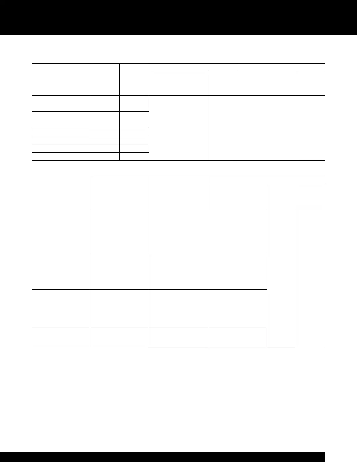
Table 21.1 Power+™, MicroVersaTrip Plus™ and MicroVersaTrip PM™ Trip Unit Characteristics
Long-time Short-time
Long Time (LT)
①
(Pickup) Delay Pickup Delay
Max. Sensor Rating Multiple of Rating Plug Amps [Band] (Multiple of Long Time) [Band]
Frame Size Amp Rating (Amps) (CT) (I
n
) (Seconds) (LT) (Seconds)
WPS-08 / WPH-08
800 150, 400, 800
Power+ Power+
WPX-08 / WPF-08 0.5 thru 1.1 in 1.5, 2.0, 2.5, 3.0, 4.0, I
2
t in
WPS-16 / WPH-16
1600 800, 1600
in steps of 0.1 5.0, 7.0, 9.0 0.40
WPF-16
[1] [2] [3] [4]
WPS-20 2000 2000
2.4, 4.9, 9.8, 20
➁
I
2
t out
WPS-32 / WPH-32 / WPX-32 3200 3200 MVT Plus/PM MVT Plus/PM [1] [2] [3]
WPS-40 / WPX-40 4000 4000 0.5 thru 1.1 in 1.5 thru 9.0 .10, .21, .35
WPS-50 / WPX-50
➃
5000 5000 in steps of 0. 05 in steps of 0.5
Adjustable Adjustable
Ground Fault
Instantaneous Instantaneous Delay
Pickup without ST Pickup with ST Pickup without I
2
t
(Multiple of Rating Plug Amps) (Multiple of Rating Plug Amps) (Multiple of Sensor Amp rating)
Delay with I
2
t [Band]
Frame Size (I
n
)(I
n
) (CT) (Seconds) (Seconds)
➂
WPS-08 Power+ Power+
WPH-08 Power+ 1.5, 2.0, 3.0, 5.0, 7.0, .20, .25, .30, .35,
WPX-08 1.5, 2.0, 3.0, 5.0, 9.0, 10.0, 13.0, 15.0 .40, .45, .50, .60
WPF-08 7.0, 9.0, 10.0,
WPS-16 / WPH-16 MVT Plus/PM MVT Plus/PM
WPF-16 1.5 thru 15.0 in steps of 0.20 thru 0.60 in steps of
WPS-20 0.5 0.01
Power+ Power+ .44
MVT Plus/PM 1.5, 2.0, 3.0, 5.0, 7.0, .20, .22, .24, .26, at 200%
WPS-32 / WPH-32 1.5 thru 10.0 in steps of 9.0, 10.0, 13.0 .28, .30, .34, .37 of pick up [1] [2] [3]
WPX-32 0.5 MVT Plus/PM MVT Plus/PM at lower .10, .21, .35
1.5 thru 13.0 in steps of 0.20 thru 0.37 in steps of limit
0.5 0.01 of band
Power+ Power+ Power+
1.5, 2.0, 3.0, 1.5, 2.0, 3.0, .20, .22, .24,
WPS-40 5.0, 7.0, 9.0 5.0, 7.0, 9.0 .26, .28, .30
WPX-40 MVT Plus/PM MVT Plus/PM MVT Plus/PM
1.5 thru 9.0 in steps of 1.5 thru 9.0 in steps of 0.20 thru 0.30 in steps of
0.5 0.5 0.01
WPS-50 MVT Plus/PM MVT Plus/PM MVT Plus/PM
WPX-50
➃
1.5 thru 7.0 in steps of 1.5 thru 7.0 in steps of 0.20 thru 0.24 in steps of
0.5 0.5 0.01
①
Time delay shown at 600% of current setting at lower limit of band. (X) I
n
= Rating plug amps
➁
Time delay shown at lower limit of each band. All pickup tolerances are ±10%. (S) CT = Sensor amp rating
➂
Time delay shown at lower limit of band. Ground-fault pickup not to exceed 1200 amps. (C) LT = Long-time current setting
➃
Power+ not available on 5000 amp (WP-50) circuit breaker. ST = Short Time function