Ground-Fault Protection (Optional)
Ground-Fault Protection
A ground fault is an unintentional current flow from a
circuit through a conductive path to ground. Ground
faults usually have intermit-
tent or very low values of
current flow as depicted in
Graph A , and are not
detected by long-time over-
load protection. Some
ground-fault trip systems
may not detect this type of
fault because the intermit-
tent nature of the fault
never exceeds the trip
threshold as illustrated in Graph B . The MicroVersaTrip
Plus™ and MicroVersaTrip PM™ trip units detect and
integrate (add a series of arcing and intermittent current
pulses) the low-level current of a ground fault. This integra-
tion function provides a memory response for ground faults
to achieve preferred ground fault protection as shown in
Graph C . The NEC requires that the maximum ground-
fault setting not exceed 1200 amps. Ground-fault protection
includes independent pickup and delay settings and
selectable I
2
t function.
Ground-fault pickup settings are based on multiples of CT,
the current sensor rating. The lowest setting is 20% of CT,
and the highest setting is based on current sensor amp rat-
ings, such that the maximum setting does not exceed 1200
amps. There are three ground-fault delay bands of 1 (MIN),
2 (INT), 3 (MAX) ranging from 100 ms to 350 ms. The I
2
t
function modifies the square corner of the ground-fault
time current curve transition, from pickup to the constant
delay bands, to improve coordination with downstream
devices.
Ground-fault pickup and ground-fault time delay
20
Trip Characteristics — MicroVersaTrip Plus™ and PM™ (cont.)
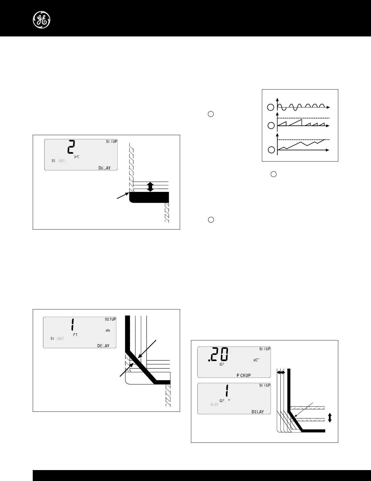
• Short-Time Delay
Short-time delay is always provided when short-time
pickup is ordered. Short-time delay provides additional
refinement for coordination between upstream and
downstream protective devices. There are 3 time delay
bands that provide delays from 100msec to 350msec
corresponding to trip unit settings of 1 (MIN), 2 (INT)
3 (MAX).
Short time delay with I
2
t OUT
Selectable Short-Time I
2
t Function
Selectable short-time I
2
t is always provided with the short-
time option. The I
2
t allows the solid-state trip unit to better
coordinate with downstream thermal magnetic devices or
fuses. This function impacts the shape of short-time pickup
and short-time delay time current curves, and may be pro-
grammed either IN or OUT.
Short time delay with I
2
t IN