D
GB
F
E
I
Ru
13
96178-06.2015-DGbFEIRu
4| Compressor assembly
4.4 Pipes
Pipesandsystemcomponentsmustbecleananddryinsideandfreeofscale,swarfandlayersof
rustandphosphate.Onlyuseair-tightparts.
Laypipes correctly. Suitable vibration compensators must be providedto prevent pipes being
crackedandbrokenbyseverevibrations.
Ensureaproperoilreturn.
Keeppressurelossestoanabsoluteminimum.
The pipe connectionshavegraduatedinsidediameterssothatpipeswith
standartmillimetreandinchdimensionscanbeused.
Theconnectiondiametersoftheshut-offvalvesareratedformaximum
compressoroutput.Theactualrequiredpipecrosssectionmustbe
matched to the output. The same applies for non-return valves.
Fig.16:graduated
internaldiameter
Fig.17
Rigid
fixed point
As short as
possible
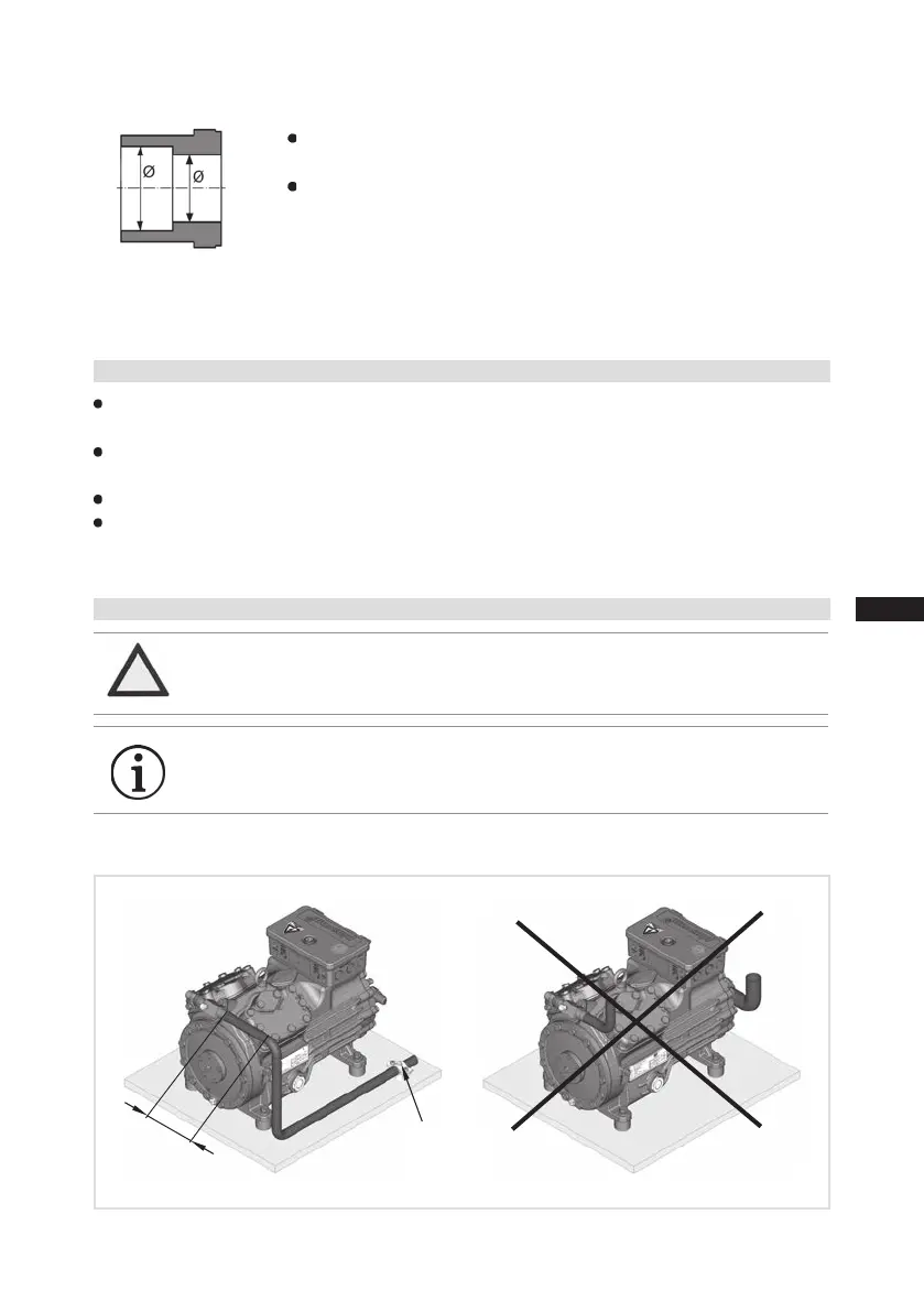
4.5 Laying suction and pressure lines
A rule of thumb:Alwayslaytherstpipesectionstartingfromtheshut-offvalvedownwards and
parallel to the drive shaft.
ATTENTION Improperly installed pipes can cause cracks and tears, the result
being a loss of refrigerant.
INFO Proper layout of the suction and discharge lines directly after
the compressor is integral to the system’s smooth running and
vibration behaviour.
 Loading...


