D
GB
F
E
I
Ru
15
96178-06.2015-DGbFEIRu
5| Electrical connection
5.1 Information for contactor and motor contactor selection
Allprotectiondevicesandswitchingormonitoringunitsmustbettedinaccordancewiththelocal
safetyregulationsandestablishedspecications(e.g.VDE)aswellaswiththemanufacturer’sinfor-
mation.Motor protection switches are required! Motorcontactors,feedlines, fuses and motor
protectionswitchesmustberatedonthebasisofthemaximumworkingcurrent(seenameplate).
Formotorprotectionuseacurrent-dependentandtime-delayedoverloadprotectiondeviceformoni-
toringallthreephases.Settheoverloadprotectiondevicesothatitmustbeactuatedwithin2hours,
ifthereis1.2timesthemax.workingcurrent.
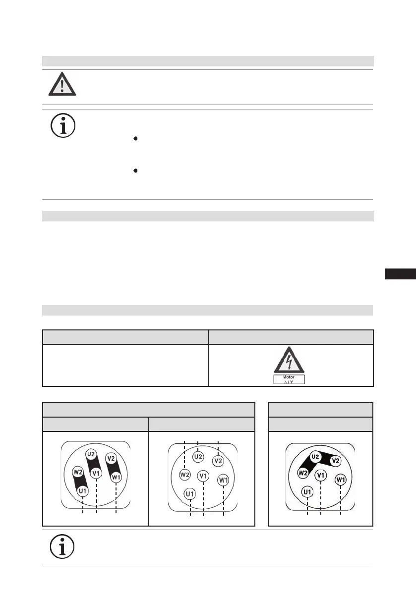
5.2 Connection of the driving motor
Thecompressorisdesignedwithamotorforstar-deltacircuits.
Designationonthenameplate Stickerontheterminalbox
∆ / Y
Star-delta start-up is only possible on 230 V voltage supply. Example:
230 V ∆
Direct start Star-delta start
400 V Y
Direct start only
Elektrischer Anschluss
Electrical connection
Raccordement électrique
∆ / Y
96027-11.06-DGbF
∆
Niedere Spannung
Low voltage
Bas voltage
Y
Hohe Spannung
High voltage
Haut voltage
L3
L1 L2
Elektrischer Anschluss
Electrical connection
Raccordement électrique
∆ / Y
96027-11.06-DGbF
∆
Niedere Spannung
Low voltage
Bas voltage
Y
Hohe Spannung
High voltage
Haut voltage
L3
L1 L2
L3
L1 L2
L1
L2
L3
L1
L2
L3
INFO
Connectthecompressormotorinaccordancewiththecircuitdiagram
(seeinsideofterminalbox).
Usesuitablecableentrypointofthecorrectprotectiontype(see
nameplate)forroutingcablesintotheterminalbox.Insertthestrain
reliefsandpreventchafemarksonthecables.
Comparethevoltageandfrequencyvalueswiththedataforthe
mainspowersupply.
Only connect the motor if these values are the same.
DANGER Risk of electric shock! High voltage!
Only carry out work when the electrical system is disconnected
from the power supply!
5 Electrical connection
INFO The connection examples shown refer to the standard version. In
thecaseofspecialvoltages,theinstructionsafxedtotheterminal
box apply.

 Loading...

