22
D
GB
F
E
I
Ru
96178-06.2015-DGbFEIRu
5.8 Electronic trigger unit INT69 G
5.9 Connection of the trigger unit INT69 G
The compressor motor is tted with cold conductor temperature sensors (PTC) connected to the
electronictriggerunitINT69G in the terminal box. In case of excess temperature in the motor
winding,theINT69Gdeactivatesthemotorcontactor.Oncecooled,itcanberestartedonlyifthe
electroniclockoftheoutputrelay(terminalsB1+B2)isreleasedbyinterruptingthesupplyvoltage.
Thehotgassideofthecompressorcanalsobeprotectedagainstovertemperatureusingthermal
protectionthermostats(accessory).
The unit trips when an overload or inadmissible operating conditions occur. Find and remedy
the cause.
INFO The relay switching outputisexecutedas aoatingchangeover
contact.Thiselectricalcircuitoperatesaccordingtothequiescent
current principle, i.e. the relay drops into a the idle position and
deactivates the motor contactor even in case of a sensor break or
open circuit.
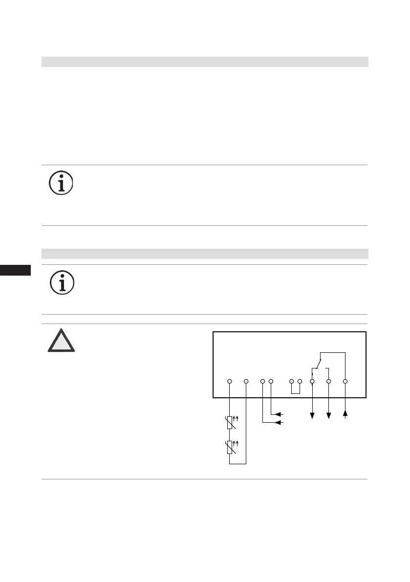
INFO Connect the trigger unit INT69 G in accordance with the circuit dia-
gram. Protect the trigger unit with a delayed-action fuse (FC2) of
max. 4 A. In order to guarantee the protection function, install the
triggerunitastherstelementinthecontrolpowercircuit.
Οnderung
Klebeschilder
0
Datum Name
Datum
Bearb.
Gepr.
Norm
1
04.12.2009
Kelich
22.05.2015
Urspr.
2
Ers. f.
3
Ers. d.
4
Schaltplan
5 6 7
BOCK COMPRESSORS
8
=
+
9
Bl.
MP10 INt69 Bl.
MP10 INt69
INT69 G
Motor Protection MP10
Steuerstrom-
kreis
L
N
Steuerstrom-
kreis
L N
1112 14
B1 B2OG OG
+
-
BT1
Θ
X1 L1 L1 N N 43 43 11 12 14
L S M
X2 1 2 3 4 5 6
R1
R2
+
-
BT1
Θ
+
-
BT2
Θ
5| Electrical connection
Terminalbox
Fig.25
ATTENTION
Measure circuit BT1 and BT2
(PTC sensor) must not come
into contact with external
voltage.
This would destroy the trigger
unit INT69 G and PTC sensors.
Controlcircuit

 Loading...

