18
D
GB
F
E
I
Ru
96178-06.2015-DGbFEIRu
5| Electrical connection
PTC1
PTC2
Terminalbox
Fig.23
5.4 Electronic trigger unit MP10
Thecompressormotoristtedwithcoldconductortemperaturesensors(PTC)connectedtotheelec-
tronictriggerunitMP10intheterminalbox.ReadinesstooperateissignalledbytheH3LED(green)
afterthepowersupplyisapplied.Inthecaseofexcesstemperatureinthemotorwinding,theunit
switchesoffthecompressorandtheH1LEDlightsred.
Thehotgassideofthecompressorcanalsobeprotectedagainstovertemperatureusingathermal
protectionthermostat(accessory).TheH2LED(red)isprovidedfortheprotectionfunction.
The unit trips when an overload or inadmissible operating conditions occur. Find and remedy
the cause.
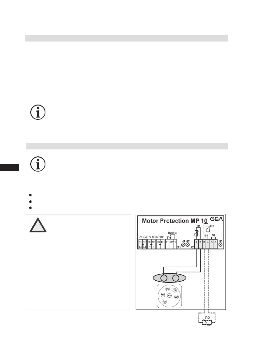
5.5 Connection of the trigger unit MP10
Temperaturemonitoringconnections:
Motorwinding: Terminals1-2
Thermalprotectionthermostat: Terminals3-4
Restartprevention: Terminals5-6
INFO
Theunithasarestartpreventiondevice.Afteryouhaverectiedthe
fault, interrupt the mains voltage. This unlocks the restart prevention
device and the LEDs H1 and H2 go out.
INFO Connect the trigger unit MP10 in accordance with the circuit dia-
gram. Protect the trigger unit with a delayed-action fuse (FC2) of
max. 4 A. In order to guarantee the protection function, install the
triggerunitastherstelementinthecontrolpowercircuit.
ATTENTION
Terminals 1 - 6 on the trigger
unit MP10 and terminals PTC 1
and PTC 2 on the compressor
terminal board must not come
into contact with mains voltage.
This would destroy the trigger
unit and PTC sensors.
The supply voltage at L1-N (+/-
for DC 24 V version) must be
identical to the voltage at termi-
nals 11, 12, 14 and 43.

 Loading...

