20
D
GB
F
E
I
Ru
96178-06.2015-DGbFEIRu
0 1 2 3 4
5 6 7 8 9
Urspr.
Ers.f.
Ers.d.
Anlagenbezeichnung
Οnderung
Vorblatt:
Datum
2INT69
Name
Bearb.
Gepr.
Norm
HG34P
R410A/Co2
200308
Kommission:
Gesamtblatt:
Datum
27.05.2015
27.05.2015
11
Kelich
Name
Zeichnungsnummer:
Kundennummer:
Kunde:
Anlage
Bl. Gruppe:
=
2INT69_24V
Ort
Bl.
Fbl.
+
2INT69 (Ohne HA)
2INT69HR60
27.05.2015ESSG_A1_35_01D
Klemmenkasten Verdichter
A1 Alarm Motorschutz
A2 Übertemperatur BT1, BT2
A3 Alarm Hochdruck
INT69 G
BT1
FC1
I>
I>
I>
QA2
PE
FC1
A1
FC2
SF1
A2
BP1
P
PE
A3
BP2
P<
PE
QA2
1
2
EB1
QA2
3 4
L1
L2
L3
L1.1
N
PE
1112 14
L N B1 B2
-EC1
3~
M
Θ
BT2
L1 L2 L3 N
PE
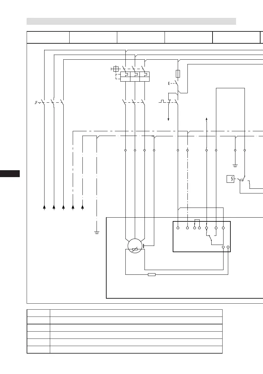
5.7 Circuit diagramm for direct start 230 V ∆ / 400 V Y --> compressor with INT69 G
Fig.24
BT1 Coldconductor(PTCsensor)motorwinding
BT2 Thermalprotectionthermostat(PTCsensor)
FC1 Loadcircuitsafetyswitches
FC2 Controlpowercircuitfuse
BP1 Safetychain(high/lowpressuremonitoring)
BP2 Releaseswitch(thermostat/pressostat)
Compressorterminalbox

 Loading...

