24
D
GB
F
E
09726-06.2018-DGbF
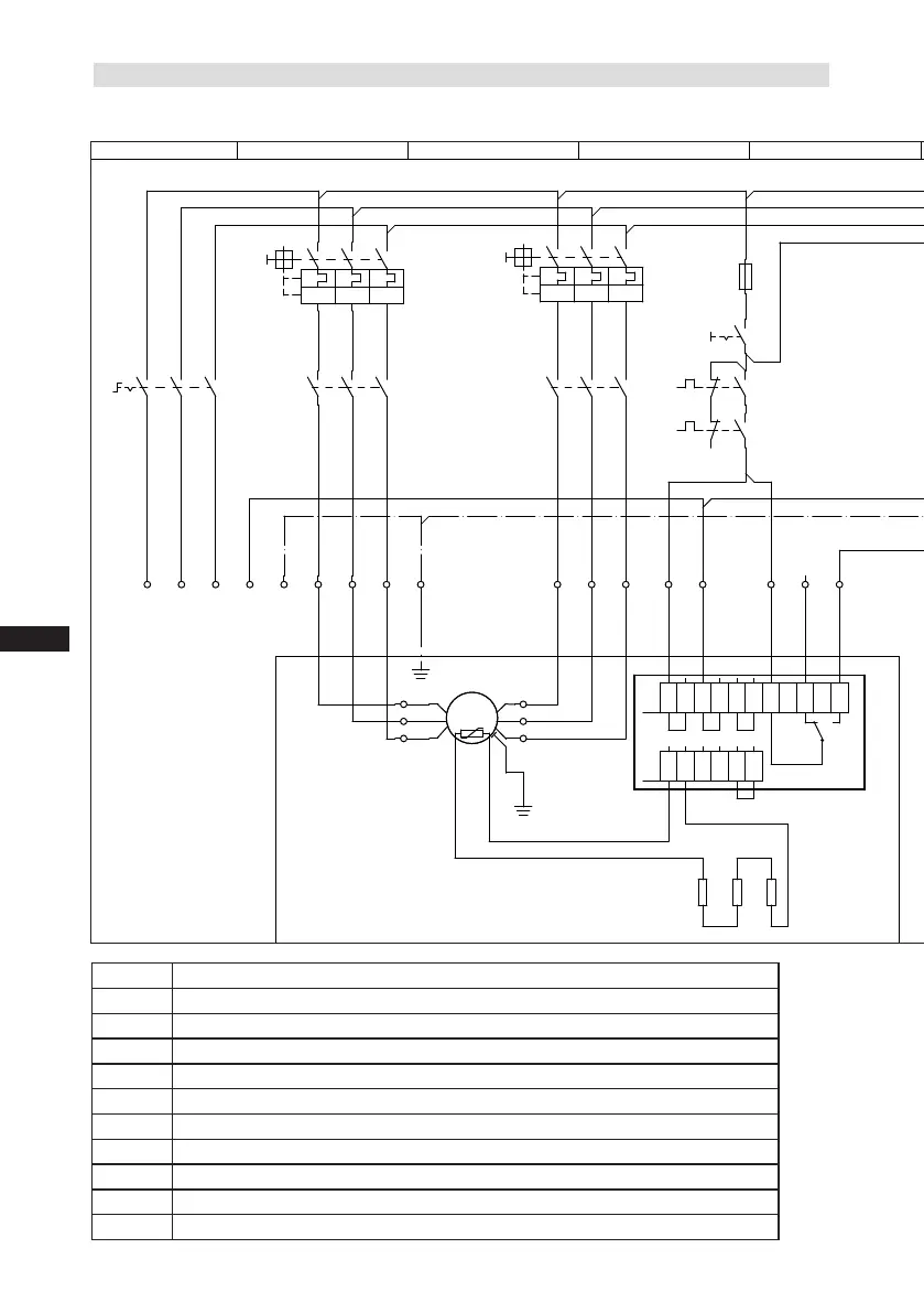
6.2 Circuit diagram for part-winding start
Fig. 31
QA1
Main switch
FC1.1 Motor protection switch part winding 1
FC1.2 Motor protection switch part winding 2
FC2 Fuse control current circuit
BP2 High pressure safety monitor
BP3 Safetychain(high/lowpressuremonitoring)
BP1 Oil differential pressure monitor
SF1 Control voltage switch
BT3 Release switch(thermostat)
QA2
Mains contactor
part winding
1
QA3
Mains contactor
part winding
2
0
Datum Name
Datum
Bearb.
Gepr.
Norm
1
20.02.2009
bauknecht
08.03.2017
Urspr.
2
3
4
HGZ7/HGZ76e
5 6 7
BOCK COMPRESSORS
8
=
+
9
Bl.
6HGZ76e Bl.
6HGZ76e
X SS
Anschlußkasten Verdichter
BT1
MP10
L1 L2 L3 N PE
FC1.1
I>
I>
I>
1
2
QA2
1
3
4
2
5
6
3
1U1
1V1
1W1
PE
2U1
2V1
2W1
FC1.2
I>
I>
I>
1
2
QA3
4
3
4
5
5
6
6 7
FC1.1
FC1.2
8
FC2
SF1
9 10
11
QA2
12
T2
13
N
14
L
15
M
16
S
BP2
P>
17 18 19
QA2
BP3
P
20
QA2
KF1
QA3
5HGZ76e.7
21
22
KF1
5HGZ76e.7
23
24
QA2
25
EB1
26
L1.1
L2.1
L3.1
L1.2
N
PE
BT3
EC1
M
Y/YY
X1 L1 L1 N N 43 43 11 12 14
L S M
X2 1 2 3 4 5 6
Compressor terminal box

 Loading...

