36
D
GB
F
E
09726-06.2018-DGbF
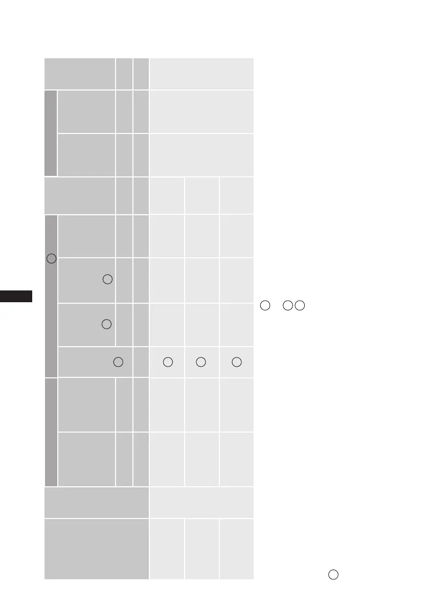
9| Technical data
1
2
3
4
*
PW = Part Winding, motors for part winding starting
1 = 1. part winding, 2 = 2. part winding
¹
)
For solder connections ²
)
in standard design
LP = Low pressure stage HP = High pressure stage
Oil sump heater:230V-1-50/60Hz140W
Tolerance(±10%)relativetothemeanvalueofthevoltagerange.
Takeaccountofthemax.operatingcurrent/max.powerconsumption
for design of fuses, supply lines and safety devices.
Allspecicationsarebasedontheaverageofthevoltagerange
380-420VY/YY-3-50HzPW,440-480VY/YY-3-60HzPW
> Winding ratios:50%/50%
HGZ7/1620-4
6
93,7/46,9 112,5/56,2 50 27,0 175/269 294
35(1
3
/
8
) 54(2
1
/
8
) 4,5HGZ7/1860-4 107,6/53,8 129,1/64,6 55 30,0 175/269 290
HGZ7/2110-4 122,4/61,2 146,9/73,5
65
36,0 232/357 288
Type
No. of cylinders
50 Hz
(1450
rpm)
LP HP
60 Hz
(1740 rpm)
LP HP
Voltage
Max.
operating
current
Max.
power
consump
-
tion
Starting
current
(rotor
locked)
Weight ²
)
Discharge
line
DV
Suction
line
SV
Oil charge
m
3
/h m
3
/h A kW A kg mm(inch) mm(inch) Ltr.
*PW 1+2 *PW1/PW 1+2
Connections ¹
)
Electrical data
Displacement
3
1
4
4
4
2
2

 Loading...

