34
D
GB
F
E
09726-06.2018-DGbF
8| Maintenance
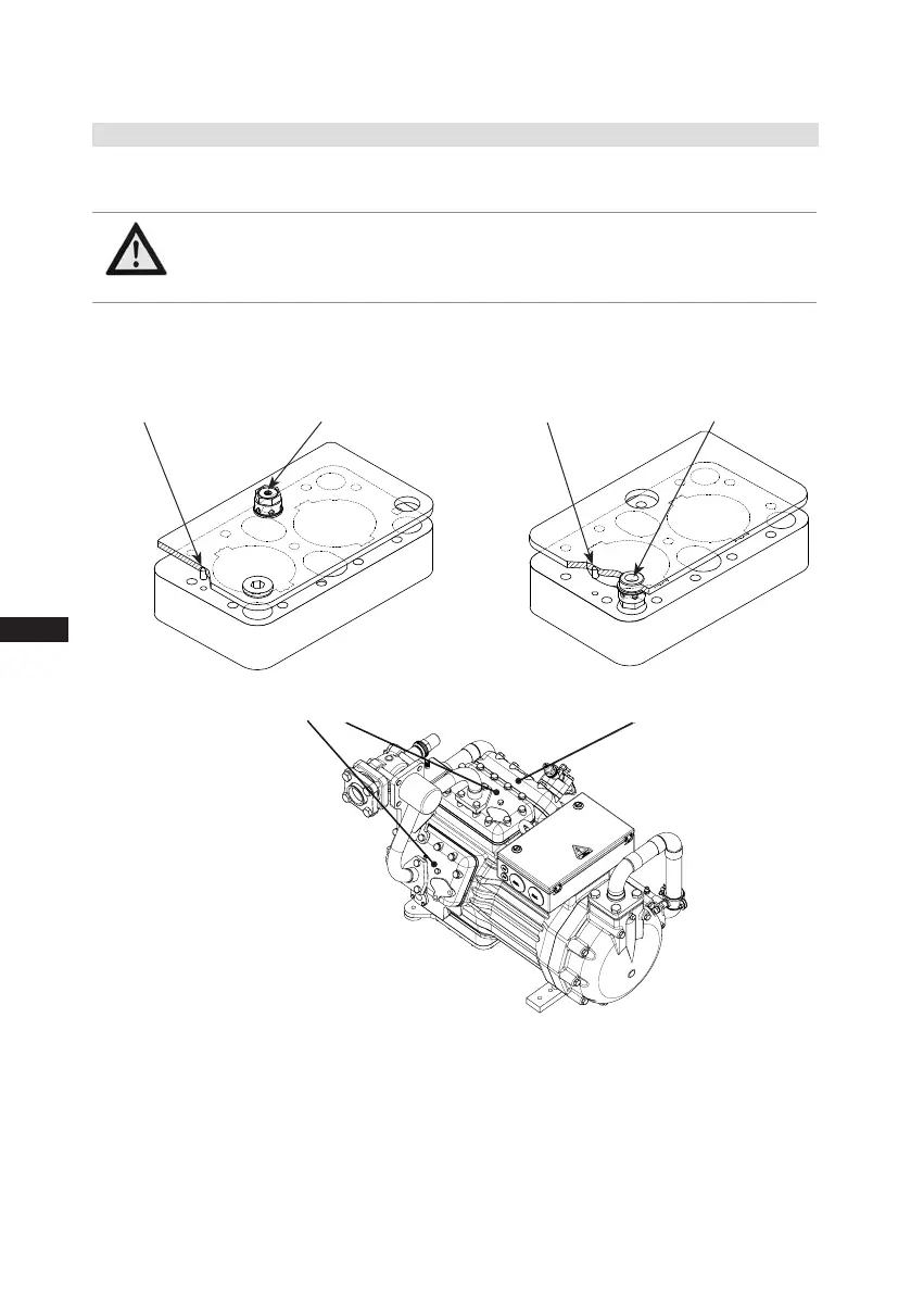
Safety valveSafety bolt
Installation of the valve plates:
Valve plate LP stage Valve plate HP stage
Safety valve
Safety bolt
8.4 Replacing the valve plates
The compressors are divided into an LP and an HP compressor stage. Different valve plate designs
arerequiredbecauseofthedifferentductsintheindividualcompressorstages.
Fig. 34
WARNING
Thevalveplateshavebeenttedwithsafetyboltstopreventanyconfusion.
The safety bolts engage in the corresponding bores on the cylinder
heads, the safety bolts must not be removed!
Ventilplatte LP-Stufe
Ventilplatte HP-Stufe

 Loading...

