D
GB
F
E
27
09726-06.2018-DGbF
6| Electrical connection
Terminal box
Fig. 32
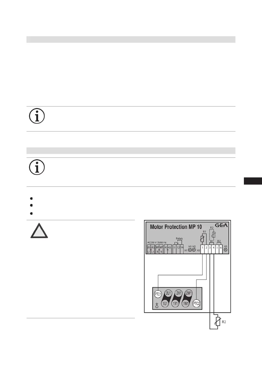
6.5 Connection of the trigger unit MP10
Temperaturemonitoringconnections:
Motorwinding: Terminals1-2
Thermalprotectionthermostat: Terminals3-4
Restartprevention: Terminals5-6
ATTENTION
Terminals 1 - 6 on the trigger
unit MP 10 and terminals PTC
1 and PTC 2 on the compressor
terminal board must not come
into contact with mains voltage.
This would destroy the trigger
unit and PTC sensors.
The supply voltage at L1-N
(+/- for DC 24 V version) must
be identical to the voltage at
terminals 11, 12, 14 and 43.
INFO
Theunithasarestartpreventiondevice.Afteryouhaverectiedthe
fault, interrupt the mains voltage. This unlocks the restart prevention
device and the LEDs H1 and H2 go out.
INFO Connect the trigger unit MP10 in accordance with the circuit
diagram. Protect the trigger unit with a delayed-action fuse (F) of
max. 4 A. In order to guarantee the protection function, install the
triggerunitastherstelementinthecontrolpowercircuit.
6.4 Electronic trigger unit MP10
The compressor motor is tted with cold conductor temperature sensors (PTC) connected to the
electronic trigger unit MP 10 in the terminal box. Readiness to operate is signalled by the H3 LED
(green)afterthepowersupplyisapplied.Inthecaseofexcesstemperatureinthemotorwinding,the
unit switches off the compressor and the H1 LED lights red.
The hot gas side of the compressor can also be protected against overtemperature using a thermal
protectionthermostat(accessory).TheH2LED(red)isprovidedfortheprotectionfunction.
The unit trips when an overload or inadmissible operating conditions occur. Find and remedy
the cause.

 Loading...

