D
GB
F
E
29
09726-06.2018-DGbF
6| Electrical connection
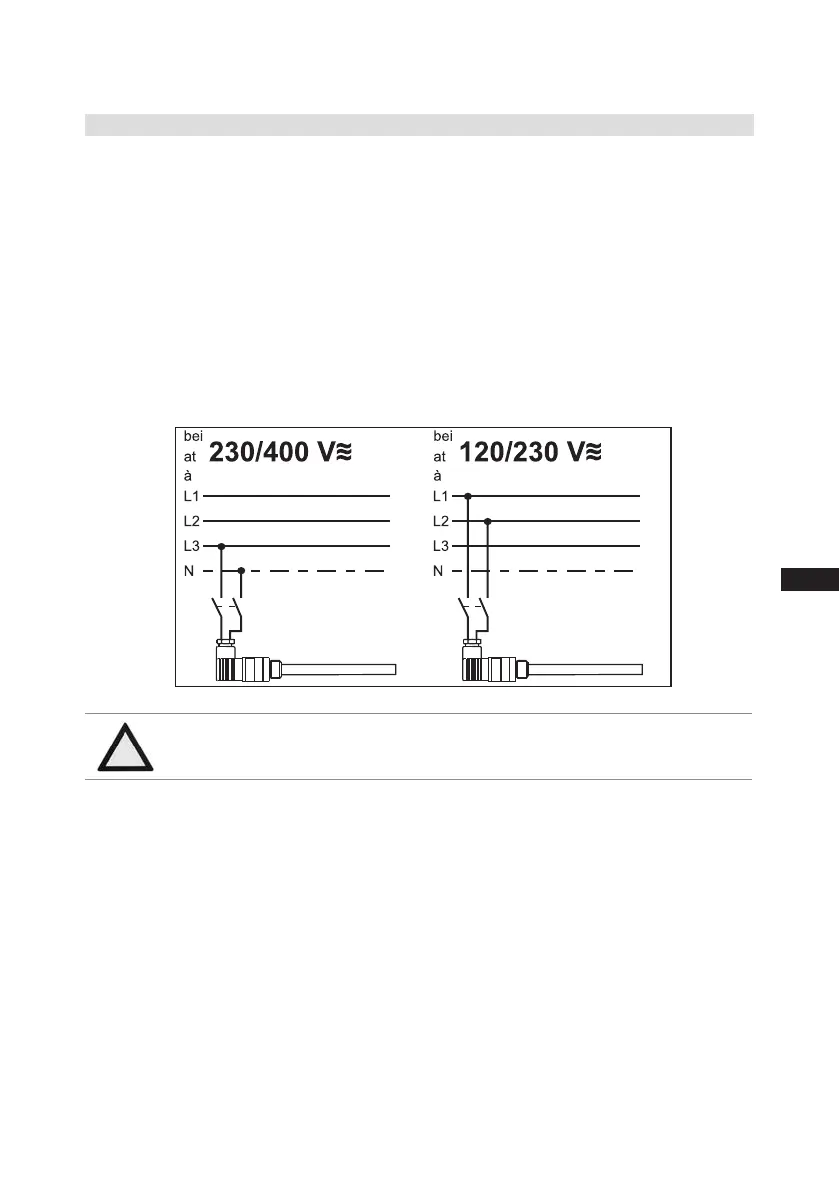
Fig. 33
Anschlussschema für Ölsumpfheizung
Connection diagramm for oil sump heater
Plan de raccordement pour résistance de carter d‘huile
09983- 10.01-DGBF
D
GB
F
6.7 Oil sump heater (accessories)
When the compressor is at a standstill, refrigerant diffuses into the lubricating oil of the compressors
housing, depending on pressure and ambient temperature. This reduces the lubricating capacity of
the oil. When the compressor starts up, the refrigerant contained in the oil evaporates out throught the
reductioninpressure.Theconsequencescanbefoamingandmigrationoftheoil,causingoilshocks
under certain circumstances.
Operation: The oil sump heater operates when the compressor is at a standstill. When the compres-
sor starts up, the oil sump heater switches off again automatically.
Connection:Theoilsumpheatermustbeconnectedviaanauxiliarycontact(orparallelwiredauxili-
arycontact)ofthecompressorcontactortoaseperateelectriccircuit.
El.data:230V-1-50/60Hz,140W.
ATTENTION The oil sump heater must not be connected to the electrical circuit
of the safety control chain.

 Loading...

