16
D
GB
F
E
I
Ru
09790-02.2018-DGbFEIRu
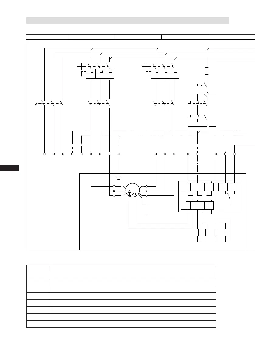
5.3 Basic circuit diagram for part winding start with standard motor
Fig. 20
15-16 Connections for PTC sensor (MP10)
R1 Cold conductor (PTC sensor) motor winding
R2 Thermal protection thermostat (PTC sensor)
F1.1
Motor protection switch
F1.2 Motor protection switch
F2 Control power circuit fuse
F3 High pressure safety monitor
F4
Safety chain (high/low pressure monitoring)
F5 Oil differential pressure monitor
P - oil
Οnderung
0
Datum Name
Datum
Bearb.
Gepr.
Norm
1
20.02.2009
Kelich
10.02.2012
Urspr.
2
Ers. f.
3
Ers. d.
4
PW MP10
5 6 7
BOCK COMPRESSORS
8
=
+
9
Bl.
4 Bl.
2
1
X SS
Anschlußkasten Verdichter
R1
MP10
F5
P-Öl
Q1
L1 L2 L3 N PE
F1.1
I=66%
I>
I>
I>
1
2
K1
1
3
4
2
5
6
3
1U1
1V1
1W1
PE
M1
M
/YYY
2U1
2V1
2W1
F1.2
I=33%
I>
I>
I>
1
2
K2
4
3
4
5
5
6
6
X1 L1 L1 N N 43 43 11 12 14
L S M
X2 1 2 3 4 5 6
7
F1.1
F1.2
8
R2.1
F2
4A
S1
R2.2
9
R2.3
10
R2.4
11
K1
12
T2
13
N
14
L
15
M
16
S
F3
P>
17 18 19
K1
F4
P
20
K1
K1T
K2
2.8
3.7
4.8
21
22
K1T
2.8
B1
P<
23 24
K1
25
E1
26
L1.1
L2.1
L3.1
L1.2
N
PE
Compressor terminal box

 Loading...