D
GB
F
E
I
Ru
17
09790-02.2018-DGbFEIRu
Οnderung
0
Datum Name
Datum
Bearb.
Gepr.
Norm
1
20.02.2009
Kelich
10.02.2012
Urspr.
2
Ers. f.
3
Ers. d.
4
PW MP10
5 6 7
BOCK COMPRESSORS
8
=
+
9
Bl.
4 Bl.
2
1
X SS
Anschlußkasten Verdichter
R1
MP10
F5
P-Öl
Q1
L1 L2 L3 N PE
F1.1
I=66%
I>
I>
I>
1
2
K1
1
3
4
2
5
6
3
1U1
1V1
1W1
PE
M1
M
/YYY
2U1
2V1
2W1
F1.2
I=33%
I>
I>
I>
1
2
K2
4
3
4
5
5
6
6
X1 L1 L1 N N 43 43 11 12 14
L S M
X2 1 2 3 4 5 6
7
F1.1
F1.2
8
R2.1
F2
4A
S1
R2.2
9
R2.3
10
R2.4
11
K1
12
T2
13
N
14
L
15
M
16
S
F3
P>
17 18 19
K1
F4
P
20
K1
K1T
K2
2.8
3.7
4.8
21
22
K1T
2.8
B1
P<
23 24
K1
25
E1
26
L1.1
L2.1
L3.1
L1.2
N
PE
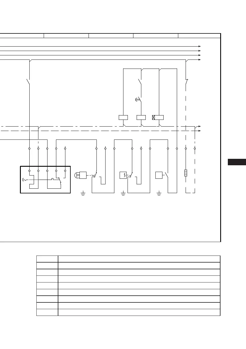
B1 Release switch (thermostat)
Q1 Main switch
M1 Compressor motor
K1 Mains contactor (part winding 1)
K2 Mains contactor (part winding 2)
K1T Delay relay max. 1s
E1 Oil sump heater
S1 Control voltage switch
XSS Terminal strip in the external switch cabinet
 Loading...