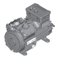
The Bock Compressor HG34P is a semi-hermetic four-cylinder reciprocating compressor designed for refrigeration systems. It features oil pump lubrication and a suction gas-cooled drive motor, making it suitable for a range of applications. The compressor is intended for installation in machines within the EU, adhering to directives such as 2006/42/EC Machinery Directive, 97/23/EC Pressure Equipment Directive, and 2006/95/EC – Low Voltage Directive.
Function Description:
The HG34P compressor operates by compressing refrigerant gas, which is then cooled by suction gas. Its four-cylinder design and oil pump lubrication ensure efficient and reliable operation. The compressor is equipped with a terminal box for electrical connections and features a nameplate that provides crucial information such as type designation, machine number, maximum operating current, starting current, maximum admissible operating pressures for both low and high-pressure sides, nominal rotation speed, displacement, oil type, and terminal box protection type.
For electrical connection, the compressor motor is designed for star-delta circuits, with specific wiring diagrams provided for direct start at 230 V Δ / 400 V Y. An electronic trigger unit MP 10 is integrated for motor protection, featuring cold conductor temperature sensors (PTC) in the motor winding. This unit signals operational readiness with a green H3 LED and indicates excess temperature in the motor winding with a red H1 LED. An optional thermal protection thermostat can be connected to protect against overtemperature on the hot gas side, indicated by a red H2 LED. The MP 10 unit also includes a restart prevention device, requiring a mains voltage interruption to reset after a fault.
Important Technical Specifications:
The HG34P series includes several models, such as HG34P/125-4, HG34P/255-4, HG34P/315-4, and HG34P/380-4, along with their "S" variants (e.g., HG34P/125-4 S) which denote more powerful motors, typically for air-conditioning applications. The "X" in the type designation (e.g., HGX34P/380-4) indicates an Ester oil charge, suitable for HFC refrigerants like R134a, R404A/R507, and R407C. For R22, a different oil type is used.
Key technical data includes:
- Displacement (50/60 Hz): Ranging from 18.8/22.6 m³/h to 33.1/39.7 m³/h.
- Voltage: 220-240 V Δ / 380-420 V Y (50 Hz) or 265-290 V Δ / 440-480 V Y (60 Hz).
- Max. Operating Current: Varies by model, e.g., 14.4/8.3 A for HG34P/215-4.
- Max. Power Consumption: Varies by model, e.g., 5.0 kW for HG34P/215-4.
- Starting Current (rotor blocked): Varies by model, e.g., 67/40 A for HG34P/215-4.
- Weight: Ranging from 91 kg to 97 kg.
- Oil Charge: 1.3 L.
- Sound Pressure Level: Typically between 62 dB(A) and 67 dB(A), depending on operating conditions (low temperature, normal cooling, air conditioning).
- Refrigerants: HFKW/HFC (R134a, R404A/R507, R407C) and (H)FCKW/(H)CFC (R22).
- Oil Types: FUCHS Reniso Triton SE 55 for HFC refrigerants and FUCHS Reniso SP 46 for R22.
Usage Features:
The compressor is designed for operation within specified limits, detailed in diagrams that highlight permissible operating ranges and areas requiring supplementary cooling or reduced suction gas temperature. Continuous operation near the limits or in shaded areas is discouraged. Important operating conditions include:
- Maximum permissible discharge end temperature of 140 °C.
- Maximum switching frequency of 8x/h.
- Minimum running time of 3 minutes under steady-state conditions.
- For frequency converter operation, maximum current and power consumption must not be exceeded.
- When operating in a vacuum range, precautions must be taken to prevent air ingress on the suction side, which can lead to chemical reactions, pressure rise, and elevated compressed-gas temperature.
Proper installation is crucial, including:
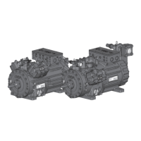
- Setting up: The compressor should be placed on an even surface or frame with sufficient load-bearing capacity. Single compressors are preferably mounted on vibration dampers, while duplex and parallel circuits require rigid mounting. Adequate clearance for maintenance and ventilation is necessary. The compressor should not be used in corrosive, dusty, damp, or combustible environments.
- Pipe Connections: Pipes and system components must be clean, dry, and free of scale or rust. Air-tight parts must be used. Proper layout of suction and pressure lines, including suitable vibration compensators, is essential for smooth running and to prevent cracks. The first pipe section from the shut-off valve should be laid downwards and parallel to the drive shaft. Soldering must be done using inert gas to prevent oxidation, and the valve body should be cooled during and after soldering. The compressor must not be under pressure during soldering.
- Shut-off Valves: Operating the shut-off valves involves releasing the valve spindle seal by approximately 1¼ turns counter-clockwise before activation, and then re-tightening it clockwise. Lockable service connections are opened by turning the spindle ½ - 1 turn clockwise.
- Commissioning: Before start-up, high-pressure and low-pressure pressostats controls are mandatory. The compressor is factory-tested, so no special running-in is required. A pressure strength test of the entire plant should be carried out with dry nitrogen (N2), ensuring the maximum permissible overpressure is not exceeded. A leak test of the refrigerating system is also required. Evacuation of the system and compressor is critical, aiming for a vacuum of <1.5 mbar when the pump is switched off. The compressor must never be started or energized under vacuum.
- Refrigerant Charge: Liquid refrigerant should be added directly to the condenser or receiver with the compressor switched off, breaking the vacuum. If topping up after starting, it can be added in vapor form on the suction side or, with precautions, in liquid form at the evaporator inlet. Overfilling must be avoided. Zeotropic refrigerant blends (e.g., R407C) must always be added in liquid form to prevent concentration shifts. Liquid refrigerant should not be poured through the suction line shut-off valve, and additives should not be mixed with oil and refrigerant.
- Start-up: Ensure both shut-off valves are open. Check all safety and protection devices. After switching on, let the compressor run for at least 10 minutes and verify the oil level in the sight glass.
- Avoiding Slugging: Proper system design, compatible component sizing, and maintaining suction gas superheating of at least 7-10 K at the compressor input are essential to prevent slugging, which can damage the compressor. Measures like liquid traps and solenoid valves in the liquid line are recommended for critical systems. No coolant movement should occur when the compressor is at a standstill.
Maintenance Features:
Regular servicing and inspection are recommended to ensure optimum operational reliability and service life.
- Preparation: Before any work, switch off the compressor, secure it against restart, relieve system pressure, and prevent air infiltration. After maintenance, reconnect the safety switch, evacuate the compressor, and release the switch-on lock.
- Oil Change: Not mandatory for factory-produced series systems. For field installations or operations near application limits, the first oil change is recommended after 100-200 operating hours, then approximately every 3 years or 10,000-12,000 operating hours. Used oil must be disposed of according to national regulations.
- Annual Checks: Include checking oil level, leak tightness, running noises, pressures, temperatures, and the function of auxiliary devices like the oil sump heater and pressure switch.
- Spare Parts: Genuine Bock spare parts are recommended. Spare parts recommendations include gasket sets, valve plate kits, and oil pump kits, with specific reference numbers for different HG34P models.
- Lubricants: The factory-filled oil type (FUCHS Reniso Triton SE 55 for HFC refrigerants or FUCHS Reniso SP 46 for R22) should be preferred. Alternative oil types are listed in the lubricants table.
- Decommissioning: Close the shut-off valves, drain refrigerant (without discharging into the environment), and dispose of it according to regulations. Once depressurized, remove fastening screws, and use an appropriate hoist to remove the compressor. Dispose of internal oil according to national regulations.