D
GB
F
E
11
09618-05.2012-DGbFEI
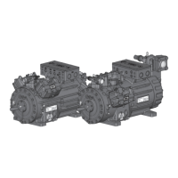
4.4 Laying suction and pressure lines
INFO! Proper layout of the suction and pressure lines directly after the
compressor is integral to the smooth running and vibration behaviour
of the system.
ATTENTION! Improperly installed pipescancause cracks and tears whichcan
resultinalossofrefrigerant,
A rule of thumb:
Alwayslaytherstpipesectionstartingfromtheshut-offvalvedownwards and
parallel to the drive shaft.
4| Compressor assembly
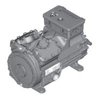
4.3 Pipes
Pipesandsystemcomponentsmustbecleananddryinsideandfreeofscale,swarfandlayersof
rust and phosphate. Only use air-tight parts.
Lay pipes correctly. Suitable vibration compensators must be provided to prevent pipes being
cracked and broken by severe vibrations.
Ensure a proper oil return.
Keeppressurelossestoanabsoluteminimum.
Fig. 13
Rigid
fixed point
As short as
possible
 Loading...