14
D
GB
F
E
96020-09.2013-DGbFEI
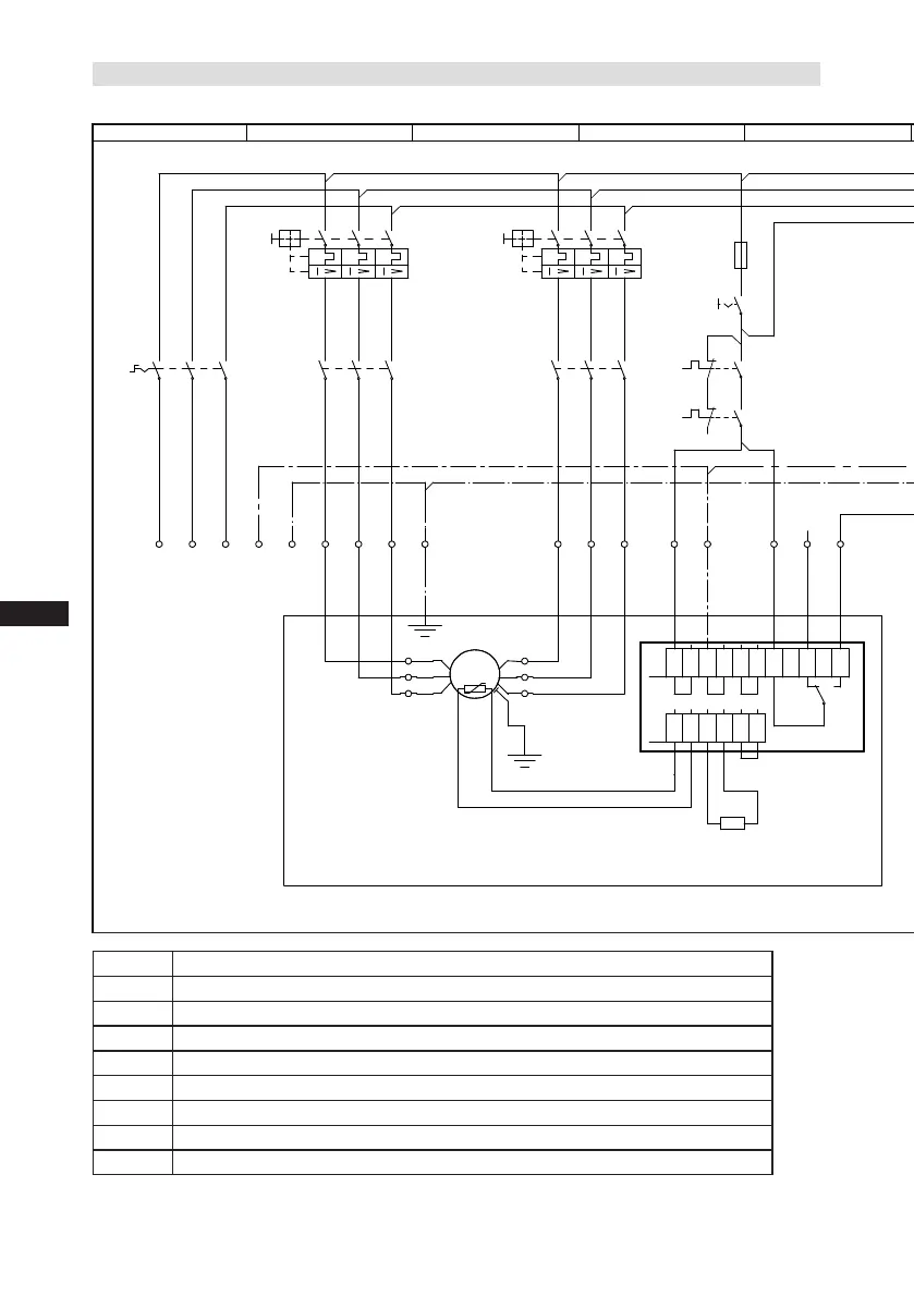
5.3 Basic circuit diagram for partial winding start with standard motor
Fig. 16
1-2 Connections for PTC sensor (MP 10)
R1 Cold conductor PTC sensor motor winding
R2 Thermal protection thermostat (PTC sensor)
F1.1/F1.2 Load circuit safety switches
F2 Control power circuit fuse
F3 / F4 Safety chain (high/low pressure monitoring)
F5 Oil differential pressure monitor
B1 Release switch (thermostat/pressostat)
Q1 Main switch
Compressor terminal box
 Loading...