D
GB
F
E
25
96020-09.2013-DGbFEI
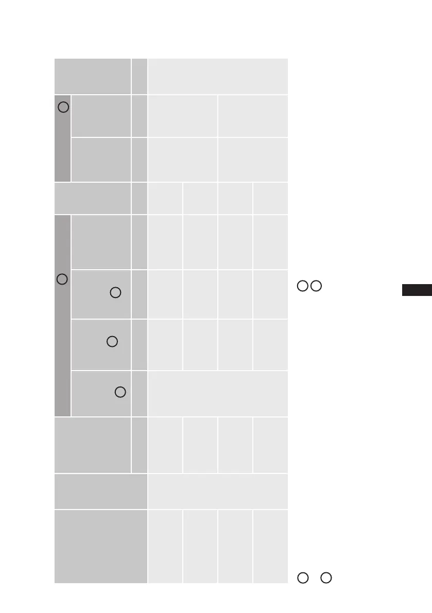
8| Technical data
Tolerance (± 10%) relative to the mean value of the voltage range.
Othervoltagesandtypesofcurrentonrequest.
-Thespecicationsformax.powerconsumptionapplyfor50Hzoperation.
For60Hzoperation,thespecicationshavetobemultipliedbythefactor
1.2. The max. working current remains unchanged.
- Take account of the max. operating current / max. power consumption for
design of fuses, supply lines and safety devices.
Fuse: Consumption category AC3
1
2
3
4
Type
No. of
cylin-
ders
Displacement
50 / 60 Hz
(1450 / 1740
rpm)
Electrical data
Weight
Connections Oil
charge
Voltage Max.
Operating
current
PW 1 + 2
Max. power
consump-
tion
Starting
current
(rotorlocked)
PW 1 / PW 1 + 2
Discharge
line
DV
Suction
line
SV
m
3
/h A kW A kg mm (inch) mm (inch) Ltr.
HGX4/310-4 CO
2
4
27,1 / 32,5 28,2 16,5 82 / 107 152
22 (
7
/
8
) 28 (1
1
/
8
)
2,7
HGX4/385-4 CO
2
33,5 / 40,2 31,6 18,5 82 / 107 151
HGX4/465-4 CO
2
40,5 / 48,6 38,3 22,3 107 / 140 154
28 (1
1
/
8
) 35 (1
3
/
8
)
HGX4/555-4 CO
2
48,2 / 57,8 38,3 22,3 107 / 140 157
1
2
3
2
4
380-420 V Y/YY - 3 - 50 Hz PW
440-480 V Y/YY - 3 - 60 Hz PW
Allspecicationsarebasedontheaverageofthevoltagerange
For solder connections
 Loading...