D
GB
F
E
11
96182-09.2013-DGbFEI
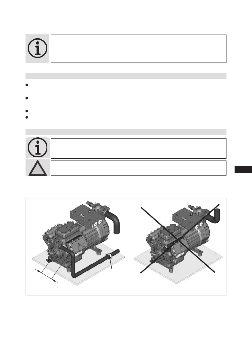
4| Compressor assembly
Rigid
fixed point
Fig.10
INFO! ForcompressorsHGX7/2110-4andHGX7/2110-4S,solderconnections
are mounted to the suction shut-off valve for pipe diameter 64.
Solder connections for pipe diameter 2 5/8“ are enclosed with the
compressor.
As short as
possible
4.4 Laying suction and pressure lines
INFO! Proper layout of the suction and pressure lines directly after the
compressor is integral to the smooth running and vibration behaviour
of the system.
ATTENTION! Improperlyinstalledpipes can cause cracks and tearswhichcan
result in a loss of refrigerant.
A rule of thumb:
Alwayslaytherstpipesectionstartingfromtheshut-offvalvedownwards and
parallel to the drive shaft.
4.3 Pipes
Pipesandsystemcomponentsmustbecleananddryinsideandfreeofscale,swarfandlayersof
rustandphosphate.Onlyuseair-tightparts.
Lay pipescorrectly. Suitable vibration compensatorsmust be provided to prevent pipes being
crackedandbrokenbyseverevibrations.
Ensureaproperoilreturn.
Keeppressurelossestoanabsoluteminimum.
 Loading...