20
D
GB
F
E
96182-09.2013-DGbFEI
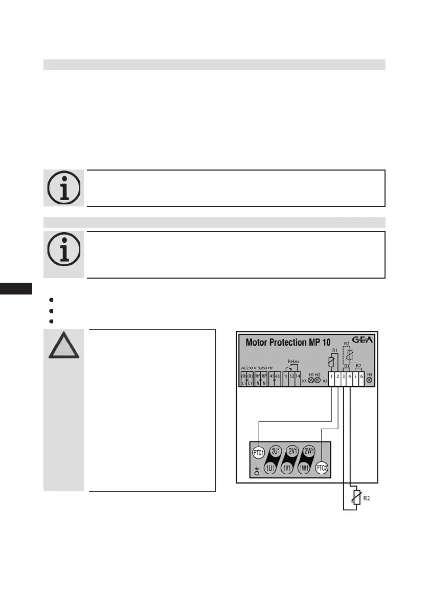
5| Electrical connection
Terminalbox
Fig.17
Temperaturemonitoringconnections:
Motorwinding: Terminals1-2
Thermalprotectionthermostat: Terminals3-4
Restartprevention: Terminals5-6
ATTENTION!
Terminals 1 - 6 on the trigger
unit MP 10 and terminals PTC
1 and PTC 2 on the compres-
sor terminal board must not
come into contact with mains
voltage. This would destroy the
trigger unit and PTC sensors.
The supply voltage at L1-N
(+/- for DC 24 V version) must
be identical to the voltage at
terminals11,12,14and43.
5.6 Electronic trigger unit MP 10
The compressor motoris tted with cold conductor temperaturesensors (PTC) connected to the
electronictriggerunitMP10intheterminalbox.ReadinesstooperateissignalledbytheH3LED
(green)afterthepowersupplyisapplied.Inthecaseofexcesstemperatureinthemotorwinding,the
unitswitchesoffthecompressorandtheH1LEDlightsred.
Thehotgassideofthecompressorcanalsobeprotectedagainstovertemperatureusingathermal
protectionthermostat(accessory).TheH2LED(red)isprovidedfortheprotectionfunction.
The unit trips when an overload or inadmissible operating conditions occur. Find and remedy
the cause.
5.7 Connection of the trigger unit MP 10
INFO! Connect the trigger unit MP10 in accordance with the circuit dia-
gram. Protect the trigger unit with a delayed-action fuse (F) of max.
4A.Inordertoguaranteetheprotectionfunction,installthetrigger
unitastherstelementinthecontrolpowercircuit.
INFO!
Theunithasarestartpreventiondevice.Afteryouhaverectiedthe
fault,interruptthemainsvoltage.Thisunlockstherestartprevention
device and the LEDs H1 and H2 go out.
 Loading...