18
D
GB
F
E
96182-09.2013-DGbFEI
nderung
1
0
Datum
Name
Datum
Bearb.
Gepr.
Norm
1
20.Feb.2009
Kelich
03.Nov.2010
Urspr.
2
Ers. f.
3
Ers. d.
4
PW MP10
5 6 7
BOCK COMPRESSORS
8
=
+
9
Bl.
2
2
X SS
Q1
L1 L2 L3 N PE
Anschluákasten Verdichter
I=66%
F1.1
K1
1
2
1
3
4
2
5
6
3
U1
V1
W1
M
3
~
M1
Y
K3
1
2
PE
R1
3
4
5
6
W2
U2
V2
I=33%
F1.2
K2
1
2
4
3
4
5
5
6
6
X1 L1 L1 N N 43 43 11 12 14
L S M
X2 1 2 3 4 5 6
7
F1.1
F1.2
8
R2
4A
F2
S1
R2
9
R2
10
MP10
11
F5
K1
12
T2
13
N
Pl
14
L
15
M
16
S
P>
F3
17
K1
K1
18
K3
19
P
F4
K4T
K3
K2
20
K4T
K2
K3
21 22
K4T
P<
B1
23 24
K1
25
E1
26
L1.1
L2.1
L3.1
L1.2
N
PE
60%
40%
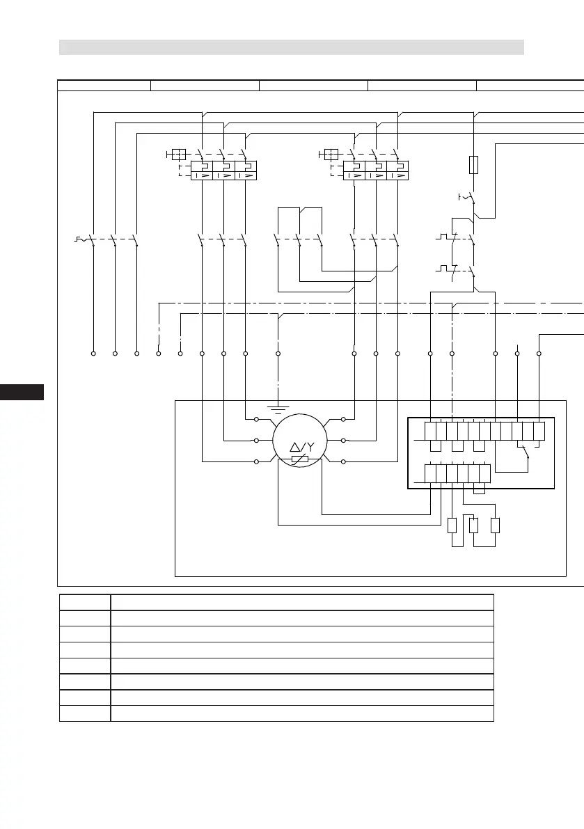
5.5 Basic circuit diagram for star delta start with special motor
Fig.16
R1 ColdconductorPTCsensormotorwinding
R2 Thermalprotectionthermostat(PTCsensor)
F1.1/1.2
2motorsafetyswitches
F2 Controlpowercircuitfuse
F3 Highpressuresafetymonitor
F4 Safetychain(high/lowpressuremonitoring)
F5 Oildifferentialpressuremonitor
B1 Releaseswitch(thermostat)
Compressorterminalbox
 Loading...