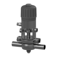
Sicherheitsventile / Safety Relief Valves
GEA Germany
GEA AWP GmbH
Armaturenstr. 2
17291 Prenzlau, Germany
Tel +49 3984 8559-0
Fax +49 3984 8559-18
info@awpvalves.com
awpvalves.com
The information contained in this brochure merely serves as a
non-binding description of our products and is without guarantee. Binding information, in particular relating to capacity data an
d suitability for specific applications, can only be provided wit
hin the framework of concrete
inquiries. Printed on chlorine
-free bleached paper · Printed in Germany · Subject to modification
8 ∙ Betriebsvorschriften / Operating Instructions
Die Haube ist mit folgendem Drehmoment anzuziehen:
! Nach jeder Demontage der Innenteile neuen O-
Ring S einbauen!
! Nach jedem Teile-Ersatz Einstelldruck [pe]
überprüfen!
Dabei ist eine Liegezeit von 48 Stunden, im montierten
Zustand, vor Überprüfung zu gewährleisten.
Die Einstellung des Einstelldruckes [pe], die
Plombierung der Einstellschraube und das Ausstellen
einer Einstellbescheinigung hat durch einen Sach-
verständigen der Technischen Überwachungsvereine
(TÜV) zu erfolgen.
Auswechseln der Druckfeder
1. Plombe und Plombendraht entfernen.
2. Haube aus Gehäuse herausschrauben (Schlüs-
selweiten siehe folgende Tabelle). Die Dichtein-
heit kpl. bzw. Spindelführung und Spindel bitte
unberührt lassen!
3. Flachdichtring K aus dem Gehäuse nehmen.
4. Kappe von der Haube schrauben, Kontermutter
linksdrehend lösen und Einstellschraube
herausschrauben (Schlüsselweiten siehe folgende
Tabelle).
Tighten the bonnet with the following torque:
! Insert a new o-ring every time the interior has
been disassembled!
! Check the test pressure [pe] every time any spare
parts have been replaced!
After the re-assembly of the valve, an idle time of 48
hours has to be observed before checking the test
pressure. The setting of the test pressure [pe], the
sealing of the adjusting screw and the issue of the
certification for the adjustment has to be done by a
surveyor of the Technical Control Board (TÜV).
How to Replace the Pressure Spring
1. Remove the seal and seal wire.
2. Unscrew the bonnet from housing (see wrench
widths in following table). Please Do not touch the
sealing unit cmpl. Resp. the stem guide and stem!
3. Remove the flat sealing ring K from the casing.
4. Unscrew the cap from the bonnet, unscrew the
back nut counter-clockwise and remove the
setting screw (see wrench widths in following
table).
Schlüsselweite
Wrench width
Anziehdrehmoment (Nm)
Torque (Nm)
Schlüsselweite
Wrench width
Schlüsselweite Kappe
Wrench width cap
Schlüsselweite Mutter
Wrench width nut
Schraube / screw
ISO 4017
Schlüsselweite Schraube
Wrench width screw
 Loading...