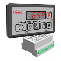
G-406-P11 SERVICE MANUAL PAGE 13
PPUH „GECO” Sp. z o.o. Edition I RELEASE DATE 2006-10-06
9. TROUBLESHOOTING GUIDE
Symptoms Remedy methods
1. The display remains dim,
but the controller is
connected to the mains.
Check:
• whether the 230 V voltage is present on the terminals L and N
• the correctness of the connection of the actuating module with the control panel
• remove and apply again the data transfer tape sockets
• connect another data transfer tape
2. The feeding screw does
not start in spite of the
fact that its activation is
signalled by the green
diode.
Check:
• whether the 230V voltage is present on the terminals in accordance with the
description provided on the upper wall of the actuating module
• feeding screw operability
• the correctness of the connection of the actuating module with the control panel
• connect another data transfer tape
3. The fan does not start in
spite of the fact that its
activation is signalled by
the green diode.
Check:
• whether the 230V voltage is present on the terminals in accordance with the
description provided on the upper wall of the actuating module
• fan operability
• the correctness of the connection of the actuating module with the control panel
• connect another data transfer tape
4. The pump does not start
in spite of the fact that its
activation is signalled by
the red diode.
Check:
• whether the 230V voltage is present on the terminals in accordance with the
description provided on the upper wall of the actuating module
• pump operability
• the correctness of the connection of the actuating module with the control panel
• connect another data transfer tape
5. Erroneous temperature
indications
Check:
• the connection of the sensors to the connector
• the correctness of the sensor fastening
• sensor cable condition; no
damages to the cable are allowed
• carefully the appearance of the external surface of the sensor shell, i.e. check for
mechanical injuries
• connect another data transfer tape
6. Controller “abnormal”
or “strange” operation
Check:
• whether the 230 V voltage is present on the terminals L and N
• the condition of feeding connectors
• the condition of wiring system and the number of equipment connected to one phase
• whether the control panel, actuating module or tapes plugs have not been exposed to
water or other liquid
• whether the control panel, actuating module or tapes plugs are not exposed to
moisture or sudden temperature fluctuations
• the correctness of the connection of the actuating module with the control panel
• connect another data transfer tape
7. Display is blinking, and
cannot be turned on
Check
• the value of the power supply voltage
• condition of the feeding connectors
• the condition of feeding connectors screwing in
• the correctness of the connection of the actuating module with the control panel
• connect another data transfer tape.

 Loading...