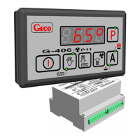
G-406-P11 SERVICE MANUAL PAGE 4
PPUH „GECO” Sp. z o.o. Edition I RELEASE DATE 2006-10-06
3. WIRING SYSTEM AND RULES OF CONNECTION
1. The boiler house should be equipped with the 230V/50Hz wiring system, in accordance with
applicable regulations.
2. Irrespective of the wiring system kind, the plug-in sockets should be equipped with the protective
terminal. The application of the socket without the protective terminal connected is a shock
hazard!
3. The controller should be connected to the separate power supply line, protected by means of the
2-4A rapid fuse and the residual current circuit breaker, with activation current 20 mA maximum.
The connection of any other equipment to this line is not allowed!
4. The clamp conductor joints used are certified for continuous load of 16 A. As the fine thread and
special metal sheets preventing conductors cutting have been applied, a perfect contact is
achieved with slight screwing of the conductor. Applying larger force may lead to breaking the
thread.
5. The power supply cables must be firmly attached along their entire length and should not catch
the water coat or the outlet to the chimney.
6. Following the connection of the unit to the power supply, the unit may be energized irrespective
of switching on or off by means of the pushbutton, therefore any repairs may be performed
only when the voltage is disconnected from the fuse!
4. A.C.U. G-406-P11 OPERATION AND ADJUSTMENT METHODS
Temperature measurement
The controller measures the temperature within the range of 0 degree Centigrade to 100 degree
Centigrade. The temperature is displayed with the delay of one second. Where the malfunction occurs to
the temperature sensor, or temperature value is found beyond the above-mentioned range and the
equipment is not found in the mode of 60 second-waiting for power supply voltage stabilization following
power failure, the controller reports the malfunction to the sensor. This causes both the deactivation of all
activated equipment, i.e. fan, electric heater, feeding screw and pump, and switching to the manual
operation mode, the following symbols being then displayed:
AL1 symbol, if the flow water temperature sensor has got broken,
AL2 symbol, if the feeding screw temperature sensor has got broken,
AL3 symbol, if the lack of fuel in the feeding screw has occurred,
The occurrence of the temperature exactly equal to 100 degrees Celsius will cause the display to show
00
o
.
Exceeding the allowable temperature of the fuel in the feeding screw
The controller has been equipped with the sensor reporting that the allowable temperature of fuel in the
feeding screw has been exceeded. The controller operates owing to the measurement of the feeding screw
pipe temperature. If the temperature in question reaches the level of 95 degrees Centigrade, the controller
reports the AL6 alarm, deactivating the fan and activating the continuous operation of the feeding screw
for the period of 20 minutes so that the burning fuel may be removed from the feeder and the furnace may
be put down.

 Loading...