GH20SB – User Manual PAGE 5
PPUH “GECO” Sp. z o.o. FROM 05/01/2015
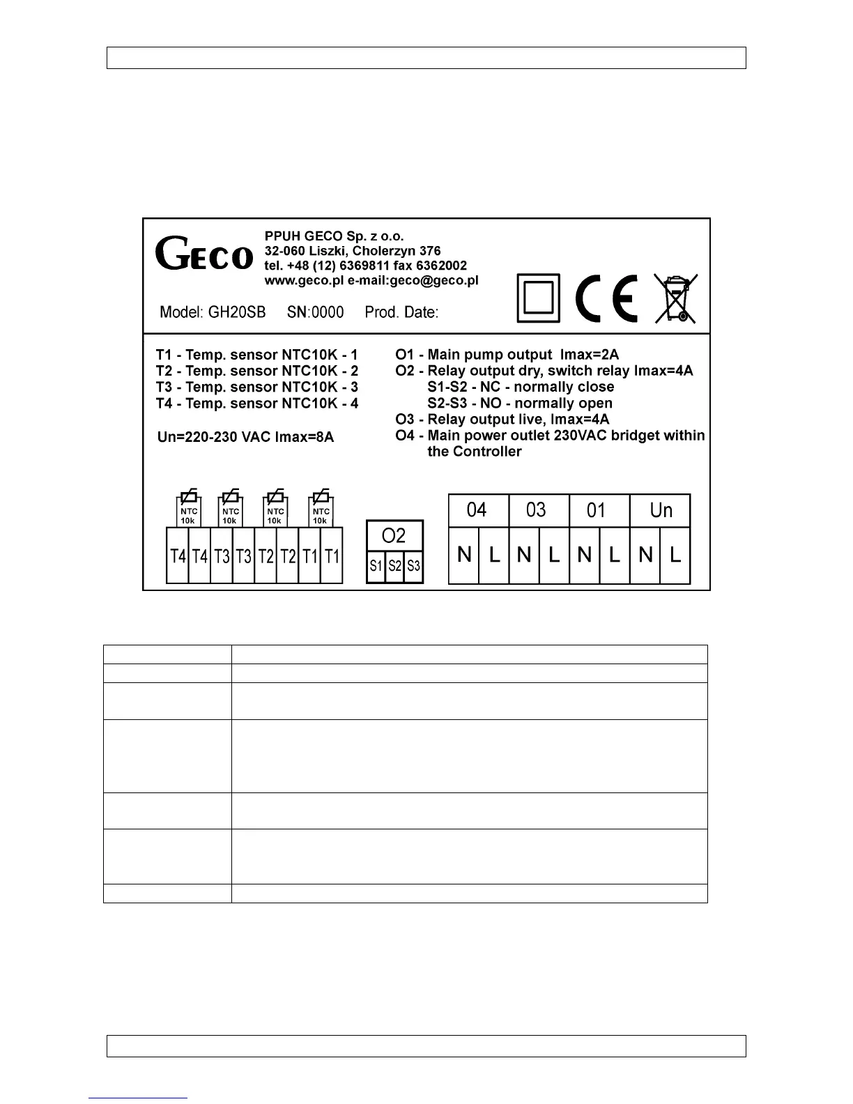
2. Connecting External Devices
The GH20SB Controller is equipped with 4 inputs enabling connection of NTC10K
temperature sensors and three outputs enabling connection of external devices, pumps or three-way
valves, depending on the system scheme chosen. A drawing contains a graphic presentation of the
input and output marking. The description of the Controller inputs and outputs is provided in the
table.
Marking of Controller inputs and outputs
Input/Output Description
Un Mains connection (230VAC~/ 50Hz)
O1 Main pump output
Maximum current rating: 3.15A
O2 Relay output – dry, switch relay
Maximum current rating: 8A
- S1-S2 – NC (normally closed),
- S2-S3 – NO (normally open).
O3 Relay output – live, 230VAC~
Maximum current rating: 8A
O4 Mains power outlet 230VAC~ bridged within the Controller. This output
may be bridged outside with the switch relay output, thus providing
switching power supply for controlling e.g. a three-way valve.
T1,T2,T3,T4 Temperature sensor inputs – NTC10k
Description of Controller inputs and outputs
When connecting devices to the Controller outputs it must be remembered that outputs
marked as O1 and O3 are live outputs to which an external device may be connected directly. The
O2 output is dry and to be placed in series between the power source and the external device.
 Loading...