GH20SB – User Manual PAGE 6
PPUH “GECO” Sp. z o.o. FROM 05/01/2015
3. Controller Usage
The GH20SB controller can’t be connection with electronic flow meter. Before
you start using controller make sure that “Measurmem” parameter is adjust to
“Rotameter”. (pkt. 3.3.4.5.)
3.1. Enabling the Controller
After connecting the Controller to the power supply, controller for about 5 second make
touch-pad keyboard calibration, and inform user about this fact by inscription on the display:
“Keyboard calibration, Do not touch sensors”
After connecting the Controller to power supply the Collector will be activated in the
standby mode (if before deactivation it was in the standby mode) or in the operation mode (if before
deactivation it was in the operation mode).
If touch sensors display doesn’t work correct please make calibration process again.
Before you start next calibration Please turn of the controller from the power supply for a moment.
3.2. Standby Mode.
In this mode the LCD display is slightly backlit and the Controller name and the current
software release are shown on the screen.
In the standby mode all outputs remain disabled and the alarm sounds are inactive.
Press to cause the Controller to exit the standby mode and switch to the operation mode.
3.3. Operation.
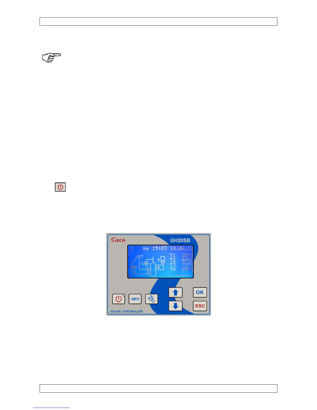
3.3.1. Main Screen.
In the upper line of the LCD display, on the left, the number of the currently supported
system scheme is shown. In the middle and on the right the time and date are shown. Below the
time and date line, on the left, the system scheme and the collector pump control level are
displayed. The digits in the scheme represent the numbering of the temperature sensors. You need
to ensure that the sensors are properly installed, as described in the scheme. Sensor substitution may
result in control system malfunction.
On the right of the system scheme the temperatures measured by sensors are shown. T1
corresponds to the temperature measured by sensor 1, T2 corresponds to the temperature measured
 Loading...