ADL500 • Quick installation guide - Specifications and connection 35
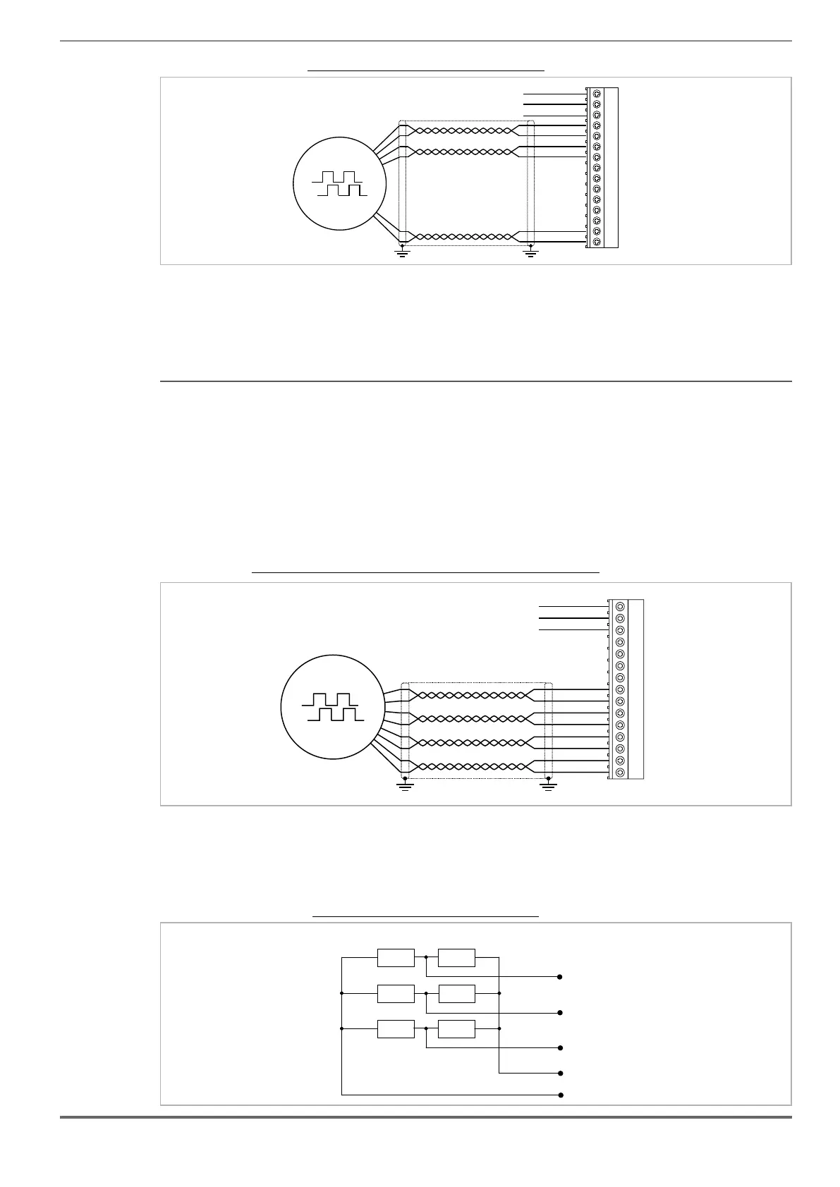
Figure 7.3.7: Connection EnDat Full Digital Encoder + 2 Freeze
DT-
DT+
CK-
CK+
0VE out
+VE out
8
9
10
11
12
13
14
15
1
2
3
4
5
6
7
(*)
XE
Fast input 2 (**)
Fast input 1 (**)
0V Fast input (**)
2 (**) on ADL550 only
(6) Connection digital Encoder 3 channels (ADL510, ADL530) - Connection digital Encoder 3 channels + 2
Freeze (ADL550) (TTL Line Driver / push pull)
Channels _______________________________ A+ A-, B+ B-, Z+ Z-, differential line drivers.
Management of loss of encoder signals (via software).
Max frequency __________________________ 100 kHz (check the number of encoder impulses according to the maximum speed)
Number of impulses ______________________ min 128, max 16384 (default 1024)
Electrical interface ________________________ TTL (ref. GND) Ulow ≤ 0.5 V Uhigh ≤ 2.5 V
Load capacity ___________________________ 13 mA @ 5.5 V (Zin 300Ω)
Programmable internal power supply __________ min +5.2 V, max +20V (default + 5.2 V) − Imax 150 mA.
The internal power supply of the encoder can be selected from the keypad (ENCODER menu,
parameter Encoder supply (PAR 2102) to balance the loss of voltage due to the length of the
encoder cable and load current.
PAR 2102 Encoder supply, range: min=5.2V, max= 20V, step of 0.1V; default=5,2V.
Cable length ____________________________ max 50m
Figure 7.3.8: Connection digital encoder 3 Channels + 2 Freeze (TTL Line Driver / push pull)
Z-
Z+
B-
B+
A-
A+
0VE out
+VE out
8
9
10
11
12
13
14
15
1
2
3
4
5
6
7
(*)
XE
Fast input 2 (**)
Fast input 1 (**)
0V Fast input (**)
2 (**) on ADL550 only
(7) Connection Single Ended Digital Encoder (ADL510-530-550)
Figure 7.3.9
3k9 1k5
8
Z- or Z+
10
B- or B+
12
A- or A+
0VEout
15
3k9 1k5
3k9 1k5
XE
+VEout