11
80546B_MHW_GF_VEDO-HL_02-2013_ENG
Nr Name Description
1 MOUSE PS/2 Mouse (green)
2 PC-KEY PS/2 keyboard (violet)
3 USB USB 2.0 Host (500mA)
4 ETH1 Ethernet 10/100 Base-T
5 KEY &LED Fieldbuses keyboard
6 POWER Power supply
7 AUTO -START Auto-on
8 EXT BATTERY External battery 3,6V
9 COM3 Serial COM3 RS485 (RS422/RS232) [optional]
10 COM2 Serial COM2 RS232 [optional]
11 COM1 Serial COM1 RS485
12 ETH2 Ethernet 10/100 Base-T
13 CAN CAN layer 2 [optional]
Table 4 - GF_VEDO HL connector description
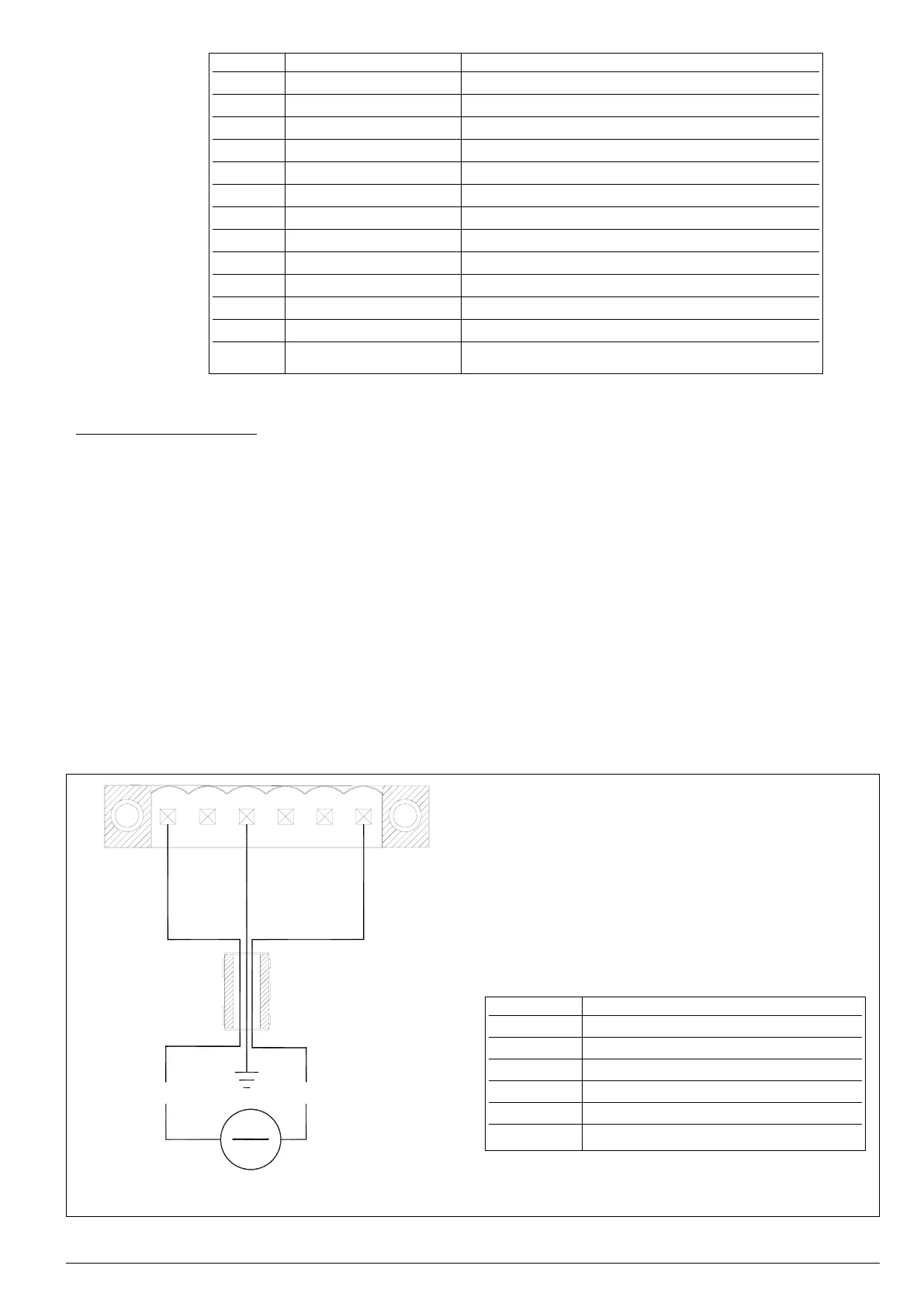
3.5.1 Power supply port
Power supply: 24VDC ±25%. The internal power supply is galvanically isolated and protected against polarity
reverses and short circuits by a resettable fuse. The panel has a power terminal. The connector diagram is shown
in Figure 8.
Note: check that the power supply is able to deliver the power needed for correct operation of the device.
The device must always be grounded. Grounding helps limit the effects of electromagnetic noise on the control
system.
All electronic devices of the control system must be grounded.
Ground the devices in a manner conforming to applicable standards and regulations.
To limit susceptibility to noise, you have to install an electromagnetic emission suppression core as shown in Figure
8.
This component, supplied with the product, is a ferrite core coated in plastic for round section wires.
Figure 8 - GF_VEDO HL power supply connector
6
1
+24VDC ± 20%
2.5A max
GND
+24V
+-
4
Pin Description
1 +24VDC Power supply Terminal
2 Not Connected
3 Not Connected
4 Ground
5 Not Connected
6 Power supply common Terminal
Table 5 - Assignment of signals to Power Supply connector of
GF_VEDO HL terminals
 Loading...