18
80546B_MHW_GF_VEDO-HL_02-2013_ENG
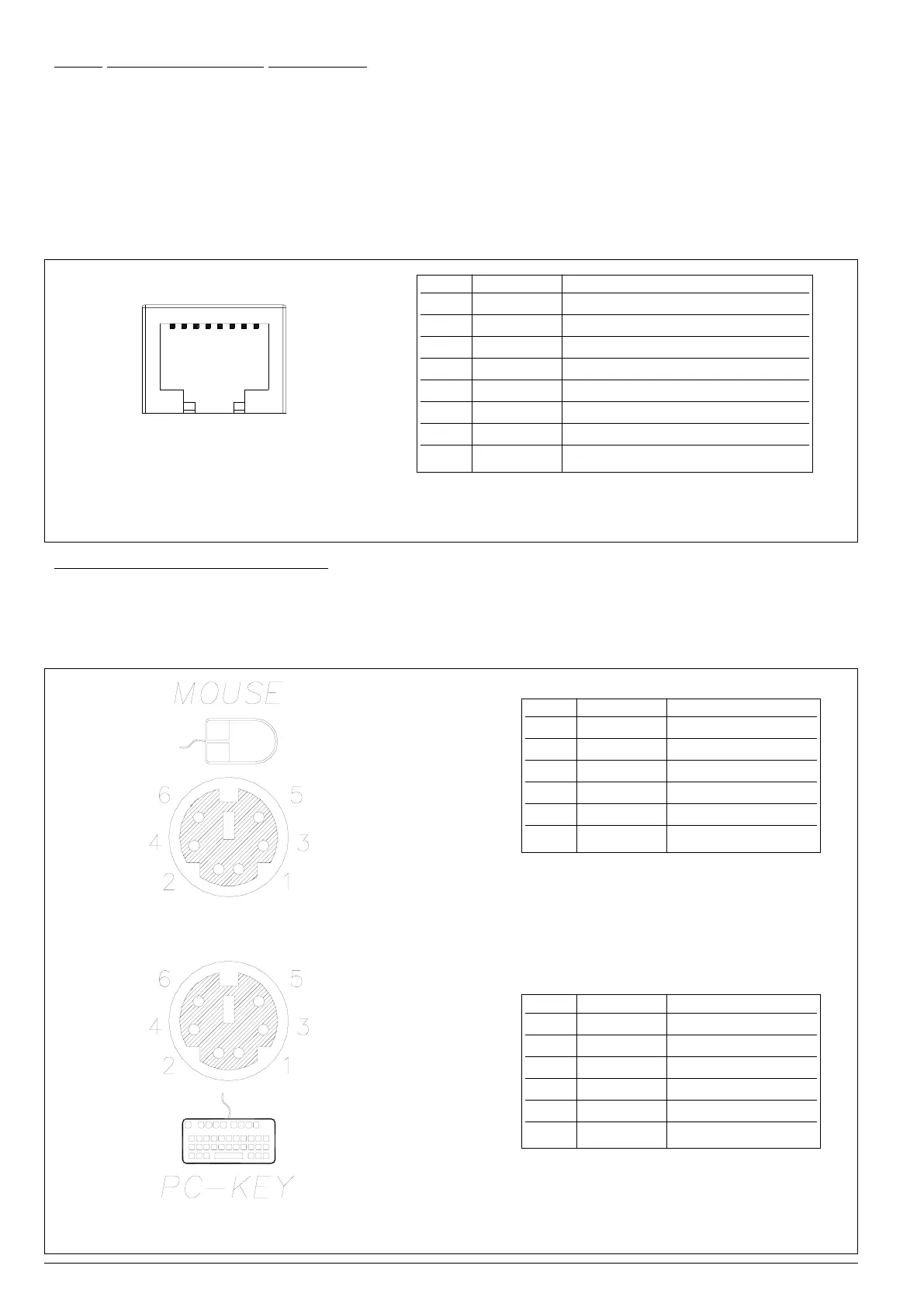
Figure 19
GF_VEDO HL KEY & LED port connector
Table 15
Signal assignment for GF_VEDO HL KEY & LED port
Pin Name Description
1 KEYCLK Keyboard clock
2 KEYOUT Keyboard output
3 KEYIN Keyboard input
4 IRST Reset GT-Tast
5 POWER +5V power supply
6 GND 0V power supply
7 GND 0V power supply
8 +12V +12V power supply
1
8
3.5.10 Matrix Keyboard port (KEY & LED)
GF_VEDO HL uses the KEY & LED port to communicate with series TF keyboards.
It uses a high-speed full-duplex synchronous serial interface (SPI) with proprietary communication protocol.
This allows scanning of the key matrix and control of off/on status of LEDs on the keyboard.
The connector is an 8-pin RJ45 without LED, which allows keyboard communication and power.
Signal assignment is shown in Table 15.
Cable length can be a maximum of 1 metre.
3.5.11 Mouse and Keyboard PS2 port
The PS2 port connects the GF_VEDO HL to keyboards and mice conforming to PS2 standard.
Two mini-DIN 6-pin female connectors are used (green: Mouse, violet: Keyboard).
Signal assignment is shown in Tables 16 and Table 17.
Figure 20
GF_VEDO HL PS2 port connector for Mouse and Keyboard
Table 16
Signal assignment for GF_VEDO HL
PS2 Keyboard port
Pin In/Out Description
1 KBD Data Data Keyboard
2 N.C. Not connected
3 GND GND
4 5 VDC +5V
5 KBD CLK Keyboard Clock
6 N.C. Not connected
Pin In/Out Description
1 MS Data Data Mouse
2 N.C. Not connected
3 GND GND
4 5 VDC +5V
5 KBD CLK Mouse Clock
6 N.C. Not connected
Table 17
Signal assignment for GF_VEDO HL
PS2 Mouse port
 Loading...