3180397M_MSW_GFX4-GFXTERMO4_08-2018_ENG
Alarm setpoints
55
A.xb1
R/W
HB alarm setpoint (scale points am-
meter input - Phase 1)
10,0
502
A.xb2
R/W
HB alarm setpoint (scale points am-
meter input - Phase 2)
10,0
With 3-phase load
503
A.xb3
R/W
HB alarm setpoint (scale points am-
meter input - Phase 3)
10,0
With 3-phase load
26
bit
HB ALARM STATE OR
POWER_FAULT
OFF = Alarm off
ON = Alarm on
R
Read state
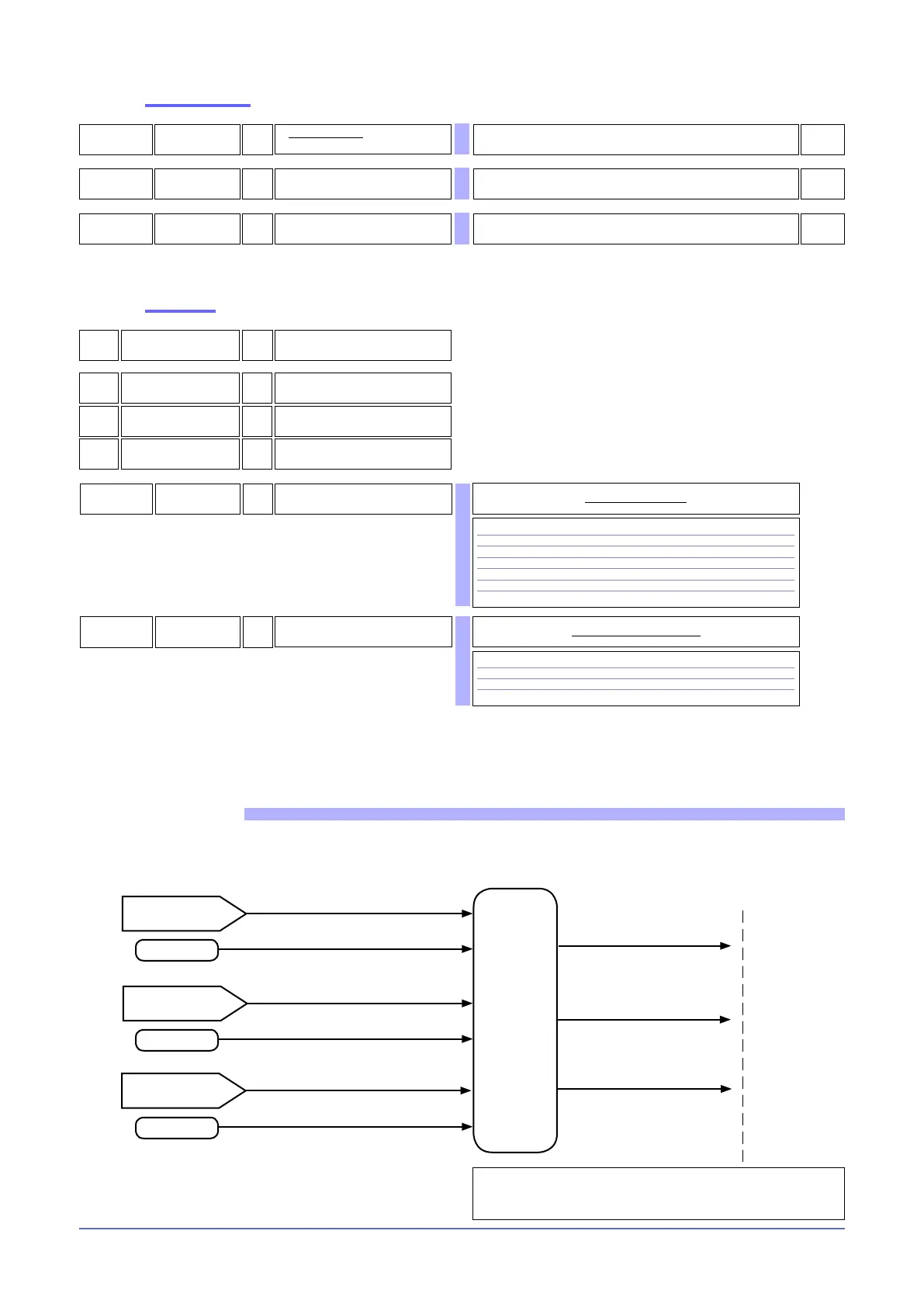
FUNCTIONAL DIAGRAM
Alarm setpoint
State of variable Hb.1
I.tA1
Function of
HB alarm
and time for
activation
of HB alarm
(Hb.F, Hb.t))
See outputs
State of variable Hb.2 (*)
Alarm setpoint
Alarm setpoint
(*) - Only for 3-phase applications
I.tAx: ammeter input
I.tA2
I.tA3
State of variable Hb.3 (*)
504
R
HB alarm states ALSTATE_HB (for
3-phase loads)
bit
0 HB TA2 time ON
1 HB TA2 time OFF
2 HB alarm TA2
3 HB TA3 time ON
4 HB TA3 time OFF
5 HB alarm TA3
Table of HB alarm states
512
R
States of alarm ALSTATE
(for single-phase loads)
bit
4 HB alarm time ON
5 HB alarm time OFF
6 HB alarm
Table of alarm states ALSTATE
76
bit
State of HB alarm
phase 1TA
R
77
bit
State of HB alarm
phase 2TA
R
78
bit
State of HB alarm
phase 3TA
R

 Loading...


