3780397M_MSW_GFX4-GFXTERMO4_08-2018_ENG
166
rL.3
R/W
Allocation of reference signal
170
rL.4
R/W
Allocation of reference signal
171
rL.5
R/W
Allocation of reference signal
172
rL.6
R/W
Allocation of reference signal
2
35
4
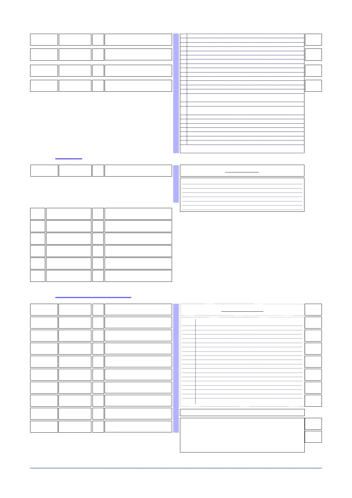
160
607
ovt.1
R/W
Allocation of physical output OUT 1
1
0 Output disabled
1 Output rL.1 zone 1
2 Output rL.1 zone 2
3 Output rL.1 zone 3
4 Output rL.1 zone 4
5 Output rL.2 zone 1
6 Output rL.2 zone 2
7 Output rL.2 zone 3
8 Output rL.2 zone 4
9 Output rL.3 OR rL.5 zone 1
10 Output rL.3 OR rL.5 zone 2
11 Output rL.3 OR rL.5 zone 3
12 Output rL.3 OR rL.5 zone 4
13 Output rL.4 AND rL.6 zone 1
14 Output rL.4 AND rL.6 zone 2
15 Output rL.4 AND rL.6 zone 3
16 Output rL.4 AND rL.6 zone 4
17 Output (rL.3 OR rL.5) zone 1...zone 4
18 Output (rL.4 AND rL.6) zone 1...zone 4
Table of output allocations
NOTE: In 3-phase conguration, the state of physical output OUT1 is copied to
OUT2 and OUT3. In 2-phase conguration, the state of physical output OUT1
is copied to OUT2 and the state of physical output OUT3 to OUT4
In case of COOL OUTPUT (5,6,7,8) are continuous, the same output functions
can not be used on other outputs.
Ex: If out.1 = 1 (out rL.1 zone 1) it is not possible to set out.5 with the same
code, if out.5 is continuous
608
ovt.2
R/W
Allocation of physical output OUT 2
2
609
ovt.3
R/W
Allocation of physical output OUT 3
3
610
ovt.4
R/W
Allocation of physical output OUT 4
4
611
ovt.5
R/W
Allocation of physical output OUT 5
5
612
ovt.6
R/W
Allocation of physical output OUT 6
6
613
ovt.7
R/W
Allocation of physical output OUT 7
7
614
ovt.8
R/W
Allocation of physical output OUT 8
8
615
ovt.9
R/W
Allocation of physical output OUT 9
17
616
ovt.10
R/W
Allocation of physical output OUT 10
18
Allocation of physical outputs
308
319
R
State of outputs rL.x MASKOUT
bit
0 State rL.1
1 State rL.2
2 State rL.3
3 State rL.4
4 State rL.5
5 State rL.6
Table of output states
12
bit
STATE rL.1
OFF = Output off
ON = Output on
R
13
bit
STATE rL.2
OFF = Output off
ON = Output on
R
14
bit
STATE rL.3
OFF = Output off
ON = Output on
R
15
bit
STATE rL.4
OFF = Output off
ON = Output on
R
16
bit
STATE rL.5
OFF = Output off
ON = Output on
R
17
bit
STATE rL.6
OFF = Output off
ON = Output on
R
Read state
+32 to reverse output status only for Logic and Relay output
2 AL1 - alarm 1
3 AL2 - alarm 2
4 AL3 - alarm 3
5 AL.HB or POWER_FAULT with HB alarm (TA1 OR TA2 OR TA3)
6 LBA - LBA alarm
7 IN1 - repetition of logic input DIG1
8 AL4 - alarm 4
9 AL1 or AL2
10 AL1 or AL2 or AL3
11 AL1or AL2 or AL3 or AL4
12 AL1 and AL2
13 AL1 and AL2 and AL3
14 AL1 and AL2 and AL3 and AL4
15 AL1 or AL.HB or POWER_FAULT with HB alarm (TA1 OR TA2 OR TA3)
16
AL1 or AL2 or (AL.HB or POWER_FAULT) with HB alarm (TA1 OR TA2
OR TA3)
17 AL1 and (AL.HB or POWER_FAULT) with HB alarm (TA1 OR TA2 OR TA3)
18
AL1 and AL2 and (AL.HB or POWER_FAULT) with HB alarm (TA1 OR TA2
OR TA3)
19 AL.HB - HB alarm (TA2)
20 AL.HB - HB alarm (TA3)
21 Setpoint power alarm
22 AL.HB - HB alarm (TA1)
23 POWER_FAULT
24 IN2 - repetition of logic input DIG2
29 Communication error
+ 32 for denied logic level at output
+ 128 to force output to zero

 Loading...


