980397M_MSW_GFX4-GFXTERMO4_08-2018_ENG
Installation of the “MODBUS” serial network
A network typically has a Master that “manages” communication by means of “commands” and Slaves that interpret
these commands.
GFX4s are considered Slaves to the network master, which is usually a supervision terminal or a PLC.
They are positively identied by means of a node address (ID) set on the rotary switches (tens + ones).
GFX4s have a ModBus serial (Serial 1) and optional Fieldbus (Serial 2) serial (see order code) with one of the fol-
lowing protocols: ModBus, Probus, CANopen, DeviceNet, Ethernet.
The following procedures are indispensable for the Modbus protocol.
For the remaining protocols, see the specic Geex Probus, Geex CANopen, Geex DeviceNet and Geex Ethernet manuals.
GFX4 modules have the following default settings:
- node address = 0 (0 + 0)
- speed Serial 1 = 19200 bit/s
- parity Serial 1 = none
- speed Serial 2 = 19200 bit/s
- parity Serial 2 = none
You can install a maximum of 99 GFX4 modules in a serial network, with node address selectable from “01” to “99” in stand-
ard mode, or create a mixed GFX4 / Geex network in Geex compatible mode in which each GFX4 identies 4 zones with
sequential node address starting from the code set on the rotary switches.
In short, the valid rotary switch settings (tens + ones) are:
- (0 +0) = Autobaud Serial 1
- (B +0) = Autobaud Serial 2
- (A + 0) = Autonode Serial 1 for Geex slaves connected to GFX4.
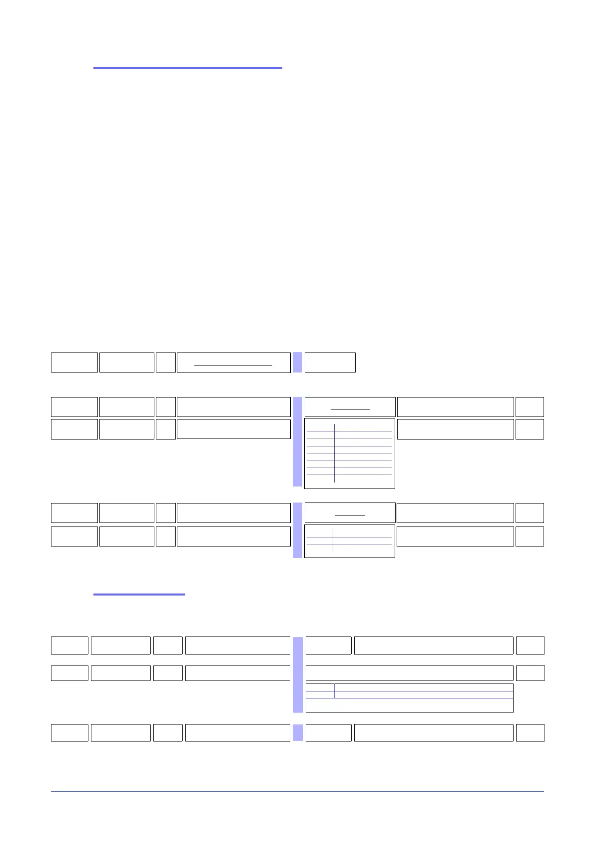
46
(od
R
Instrument identification code
1 ... 99
45
baV
R/W
Select Baudrate - Serial 1
4
0 1200 bit/s
1 2400 bit/s
2 4800 bit/s
3 9600 bit/s
4 19200 bit/s
5 38400 bit/s
6 57600 bit/s
7 115200 bit/s
Baudrate table
47
par
R/W
Select parity - Serial 1
0
0 No parity
1 Odd
2 Even
Parity table
626
bav.2
R/W
Select Baudrate - Serial 2
4
627
par.2
R/W Select parity - Serial 2
0
Communication error
If Modbus communication between GFX4 and Master node goes into timeout (settable in C.E.t parameter), you can
force an output power value (C.E.P parameter of each zone) and transmit the alarm state to a relay output (rL.x parameters).
890
[.E.T
R/W Timeout for communication error 0 ... 121 sec. Value 0 disables the function
0
891
[.E.
m
R/W Mode for communication error Mode table for communication error
0
0 Delivered power is not changed
1 La potenza erogata viene forzata al valore C.E.P
+16 only for C.M.E -1 in MANUAL_POWER at the restart of the
communication (only if in manual mode)
892
[.E.P
R/W
Output power when
communication error is active
-100.0...100.0%
0,0