1S9STOEN_26-5-17_ADL300_STO_STO Pag. 20/30
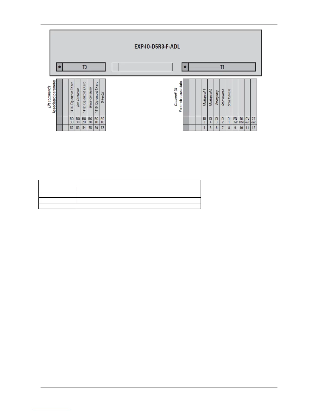
Figure 10 An example for regulation IO conFiguretion: EXP-IO-D5R3.
Regulation connector description with regard to signals related to safety function for ADL300
Advanced.
Table 7 Connector pin-out concerning safety related function onto ADL300 EXP-IO-D5R3.
Two signal inputs are provided to enable/disable STO function onto the ADL300. Both inputs are
controlled so that:
• STO function is enabled (ADL300 disabled)when either input is not excited (voltage not
applied on input).
• Both inputs will be properly excited (energized) in order for the STO function to be disabled
and ADL300 to normally operate. Table 1 specifies STO function behavior.
System also provides 2 feedback signals, which must be used according to manual and
installation guide in order to increase the safety integrity level of the system. One feedback signal
is based on a open contact relay (DRIVE OK). The other feedback signal is an opto-isolated
normally closed SAFETY OK relay which switches according to Table 4.
If any of the feedback signals does not comply with anticipated behavior a detected failure should
be assumed and countermeasures applied.
 Loading...


