www.gemu-group.com 13 / 26 GEMÜ 1235
24V / IO-Link, 3E, 4E
Electrical connection
type:
1 x 5-pin M12 plug (A-coded)
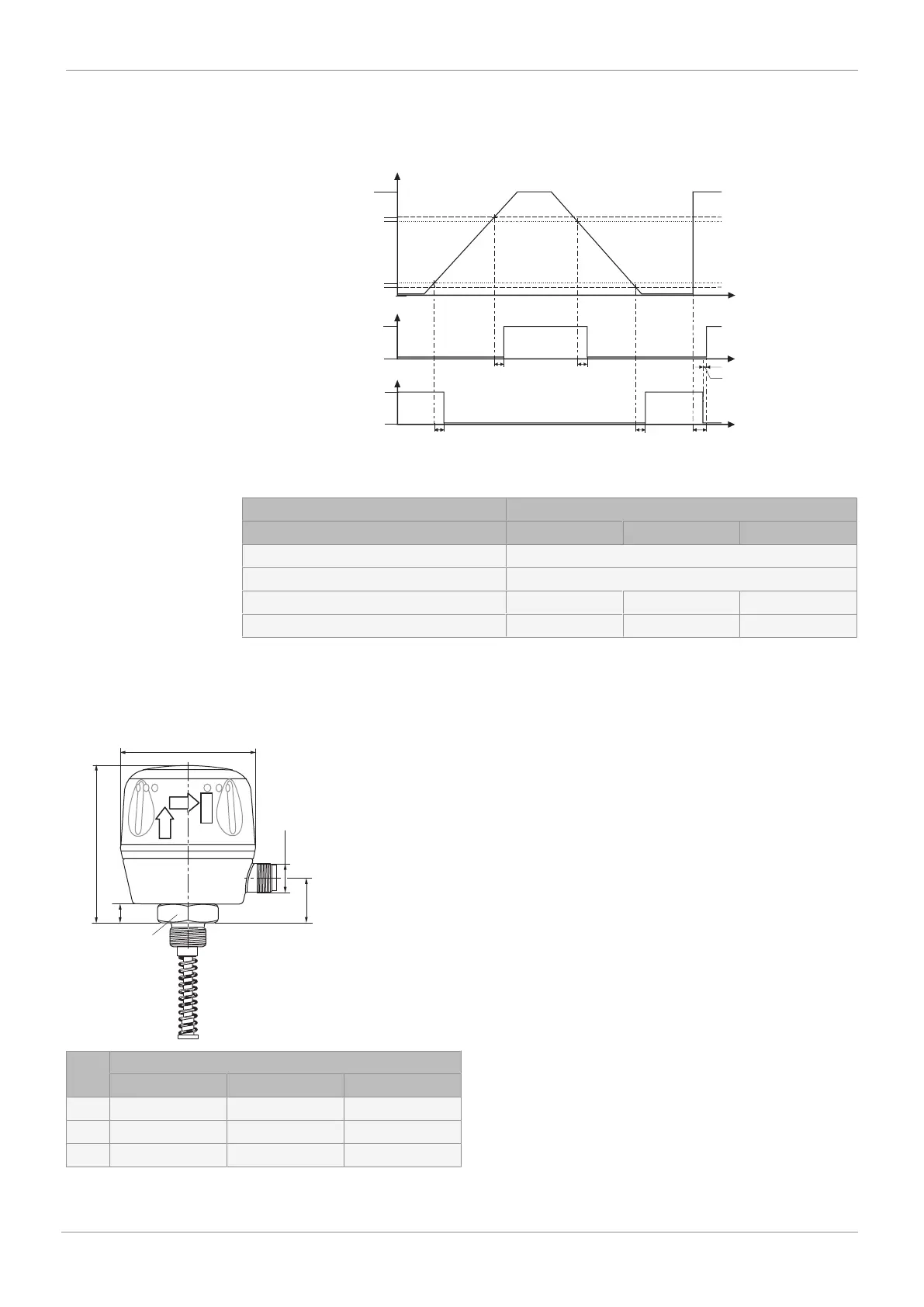
Switching characteristic:
100%
0%
td1
td1
td1
td2
td1
ta
t/ms
t/ms
t/ms
Stroke %
Switch point "Open"
Switching hysteresis
Switching hysteresis
Switching output "Open"
Switch point "Closed"
Active
Inactive
Active
Inactive
Switching output "Closed"
td1: Signal delay
td2: Signal delay
ta: Signal interval
Switch points: The data in percent refers to the programmed stroke, with reference to the lower end position (0%)
Switch points:
Travel sensor version Code
030 050 075
Default setting switch point CLOSED 12 %
Default setting switch point OPEN 25 %
Min. switch point CLOSED 0.8 mm 1.4 mm 2.0 mm
Min. switch point OPEN 0.5 mm 0.9 mm 1.25 mm
If the percentage switch points dependent on the programmed stroke are smaller than the permiss-
ible min. switch points, the min. switch points apply automatically.
8 Dimensions
PULL
TURN
PROG
A
B
SW 27
C
M12
ø 60
Travel sensor version Code
030 050 075
A 65.5 87.5 112.5
B 8.5 30.5 55.5
C 19.0 41.0 66.0
Dimensions in mm
8 Dimensions