www.gemu-group.com18 / 26GEMÜ 1235
24V / IO-Link, 3E, 4E
11 Electrical connection
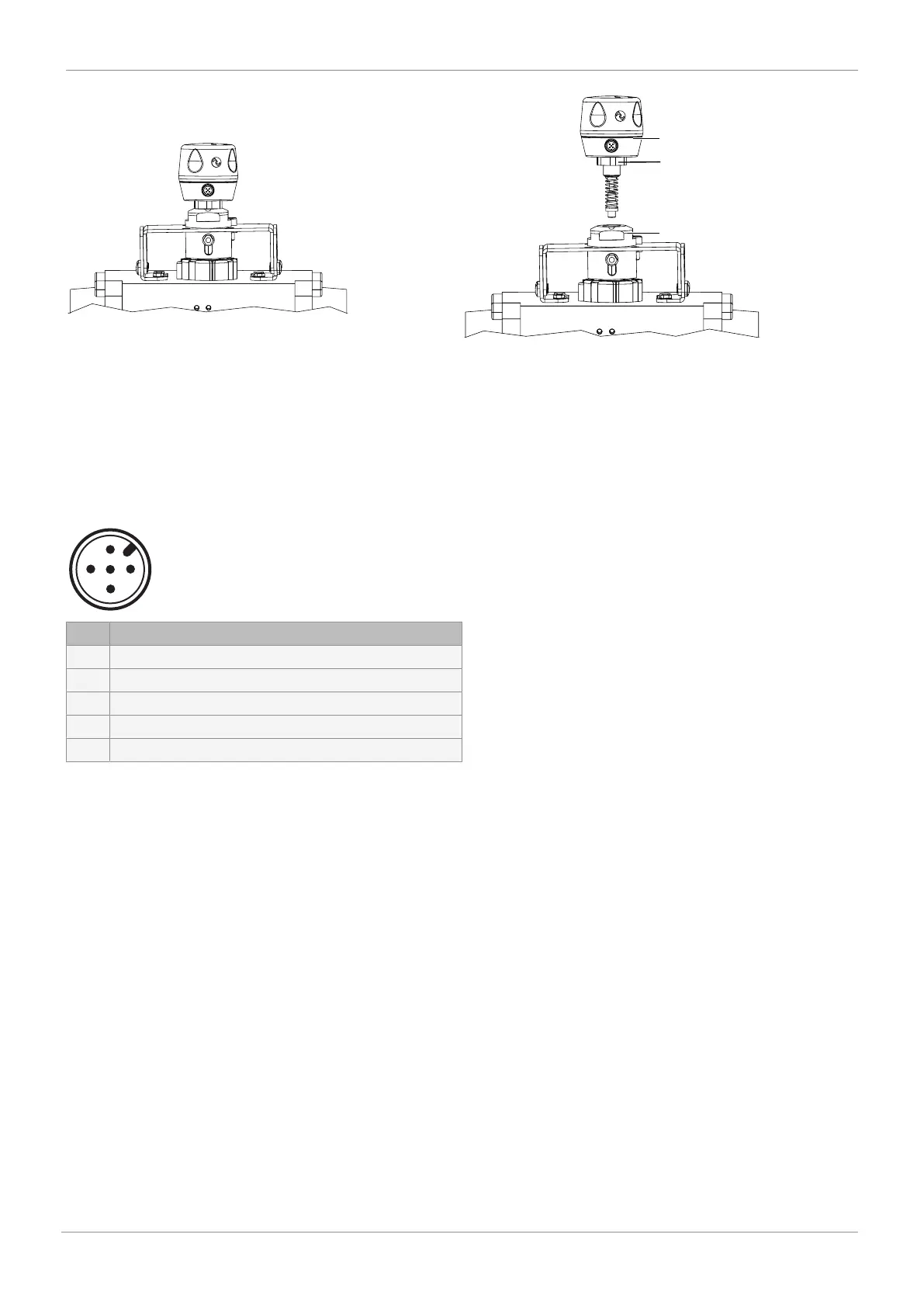
1. Screw the electrical position indicator 6 onto the adapter 7.
2. Use the spanner flat 8 (WAF 27) of the travel sensor to tighten the electrical position indicator.
3. Turn the housing clockwise to align the pneumatic or electrical connections.
4. Initialize the product.
11 Electrical connection
11.1 IO-Link, device version 3E / 4E
Description
1 U, 24 V DC, supply voltage
2 24 V DC, Open end position output
3 U, GND
4 24 V DC, Closed end position output, C/Q IO-Link
5 24 V DC, programming input (speed
AP
function)
Device version 3S / 4S is pin compatible with the previous version 2SM125, pin 5 is highly active
but without potential-free contacts. The device has 24 V DC Push-Pull outputs
12 Programming the end positions
The end positions must be programmed under the following conditions:
- Retrofitting an electrical position indicator
- Replacing the actuator
- Replacing the diaphragm
If electrical position indicators have been fitted to the process valve at the factory, the end positions will already have been pro-
grammed.
The end positions can be programmed as follows:
- On-site programming
- Programming input (pin 5)
- Communication interface
When programming via the communication interface, automatic programming is recommended.