www.gemu-group.com 17 / 26 GEMÜ 1235
24V / IO-Link, 3E, 4E
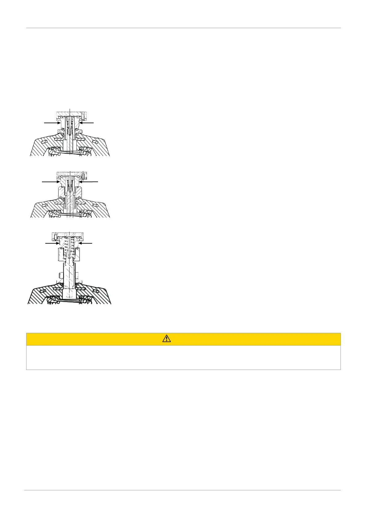
1. Move the actuator to the OPEN position.
2. Guide the product as far as it will go into the actuator opening, the adapter 3 (see “Assembling the adapter (linear actuator)“,
page15) or the stroke limiter 1 (see “Assembling the stroke limiter (linear actuator)“, page16), and screw it in clockwise
against the initial spring tension.
3. Use the spanner flat of the travel sensor to tighten the product.
4. Turn the housing clockwise to align the pneumatic or electrical connections.
5. Initialize the product.
6. The product with mounting kit is fully assembled.
7. The product with mounting kit and adapter is fully assembled.
8. The product with mounting kit and stroke limiter is fully assembled.
10.8 Installing the electrical position indicator (quarter turn actuator)
CAUTION
Incorrect installation of the product.
▶ Damage to the housing.
● Only tighten the product using the spanner flats provided for this purpose.
10 Assembly and installation