www.gemu-group.com16 / 26GEMÜ 1235
24V / IO-Link, 3E, 4E
10 Assembly and installation
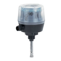
10.6 Assembling the stroke limiter (linear actuator)
5
5
4
3
2
1
6
8
9
7.1
7.2
Option1
Option2
1. Screw distance piece 5 onto/into actuator spindle 6.
2. Move the actuator to the closed position.
3. Insert the O-ring 7.1 in the stroke limiter 1.
4. Insert the O-ring 7.2 in the washer 4.
5. Screw stroke limiter 1 with nut 2, seal 3 and washer
4 into the actuator opening.
6. Set stroke limiter 1 to the required stroke.
7. Make sure that the minimum stroke is reached.
8. Secure stroke limiter 1 with nut 2.
Key
1 Stroke limiter 7.1
1)
7.2
1)
O-ring
2 Nut 8 Protective cap
3
1)
Seal 9 Position indicator
4
1)
Washer 10 Operating bush
5
2)
Distance piece 11 Spindle
6 Actuator spindle 12 Travel sensor
1) Only available for valves with the NO and DA control functions.
2) Only included in required mounting kits. The design depends on the valve.
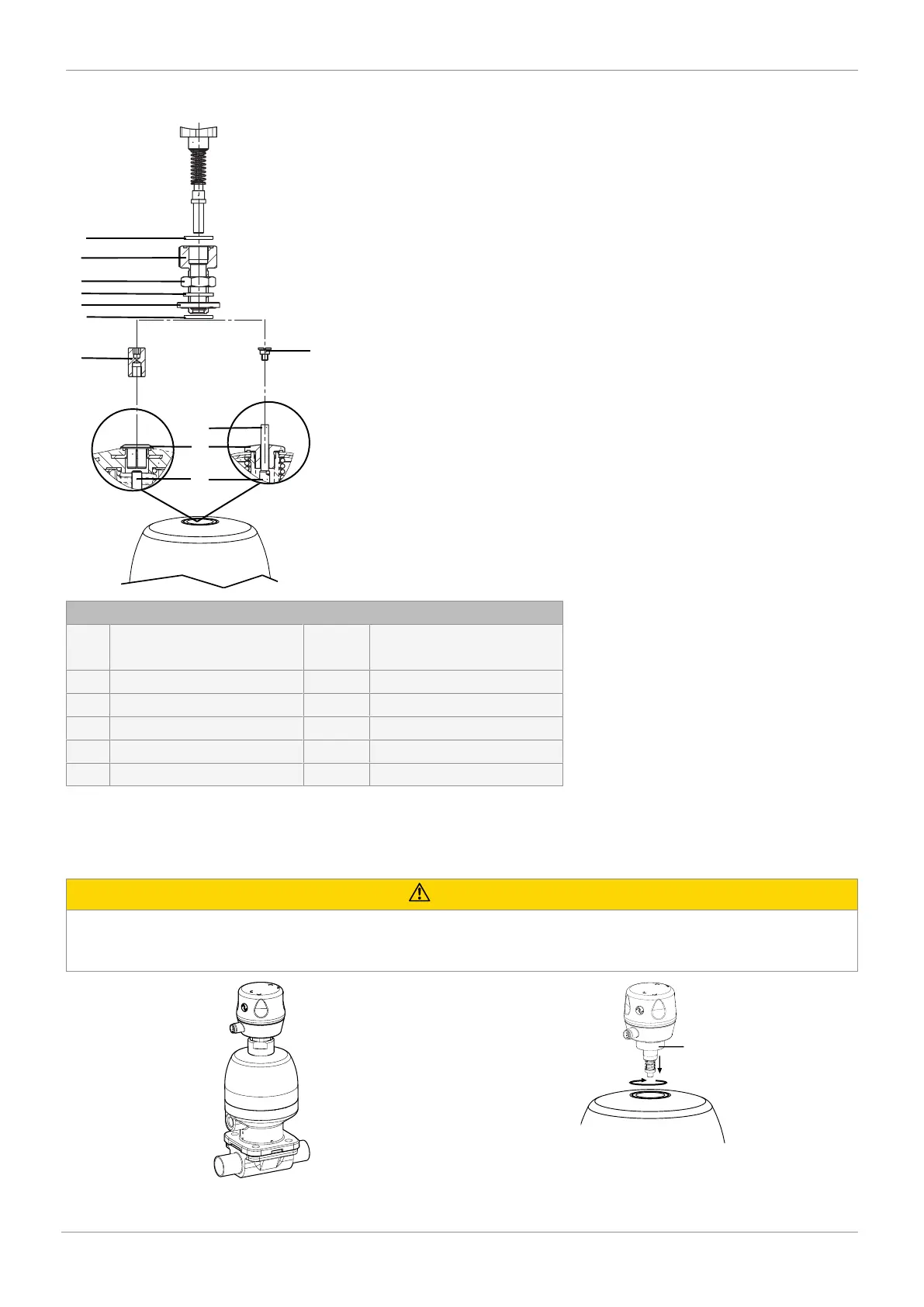
10.7 Installing the electrical position indicator (linear actuator)
CAUTION
Incorrect installation of the product.
▶ Damage to the housing.
● Only tighten the product using the spanner flats provided for this purpose.