7.6.6 Positioner data
Note: Interferences to the set value signal can affect positioner activities
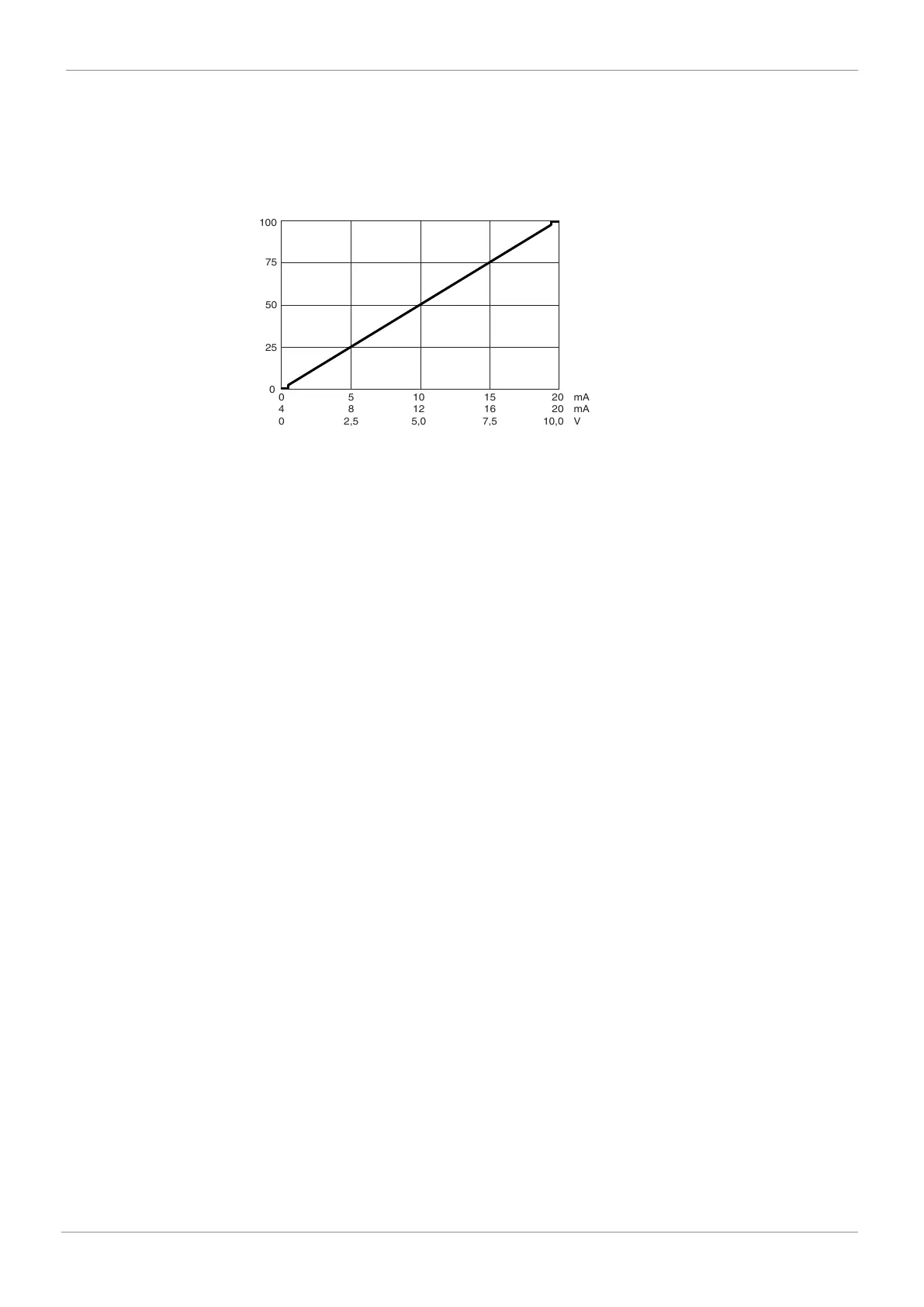
Following diagram valid for valves with standard correlation between spindle position and valve po-
sition.
(See section "Mechanical data, correlation between travel sensor spindle/valve position")
Control diagram:
0
4
0
mA
mA
V
20
20
10,0
15
16
7,5
10
12
5,0
5
8
2,5
0
75
100
50
25
The GEMÜ 1434 μPos digital electro-pneumatic positioner automatically detects the control func-
tion of the valve during initialization: Normally open (NO) or normally closed (NC).
For the 0/4 mA or 0 V signal specification, the position of the valve is closed.
The close tight function integrated as standard ensures that the valve is moved completely to the
end position when the signal Open or Close valve is given.
Control error: ≤ 1% (standard)
≤ 2% (K-no. 2442)
≤ 5% (K-no. 2443)
Initialisation: Automatic via 24 V DC signal
Close tight function: Closed: W ≤ 0.5%
Open: W ≥ 99.5%
GEMÜ 1434 µPoswww.gemu-group.com 15 / 32
7 Technical data