www.gemu-group.com 25 / 34 GEMÜ 3040
Max. range
The value at which 20 mA is to be output is set here.
Setting range: 0 to 8000 ml/s (or °C or m/s) + 0 to 900 l/min in
steps of 0.01
Factory setting: Max. flow rate value (dependent on the nom-
inal size)
For
– DN10: 350 ml/s
– DN15: 600 ml/s
– DN20: 1000 ml/s
– DN25: 4000 ml/s
– DN32 = 300 l/min
– DN40 = 480 l/min
– DN50 = 900 l/min
11.2.6.4 Digital output Q1
The digital output Q1 can be used as a pulse output, to indic-
ate the empty pipe signal, to control a dosing valve or for
monitoring of limiting values.
The output becomes high-resistance if 16 V are exceeded. In
case of a short-circuit or overloading above approx. 100 µs,
the digital output is set to high resistance for 2 s. Then a new
attempt is made to actuate the output.
Settings: Off, pulse output, empty pipe, dosing output, low set
point, high set point, negative flow
Factory setting Q1: Pulse output
Depending on the application, NPN or PNP logic can be selec-
ted.
Setting range: PNP/NPN, break contact / make contact
Factory setting Q1: PNP make contact
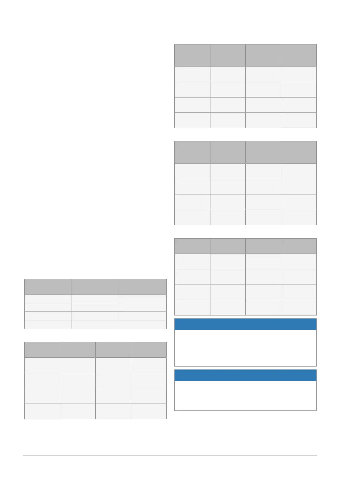
Empty pipe output
Empty metering
tube
Filled metering
tube
NPN break contact High-resistance 0 V
NPN make contact 0 V High-resistance
PNP break contact High-resistance 24 V
PNP make contact 24 V High-resistance
Pulse output
Empty meter-
ing tube
Stationary
medium
Flowing me-
dium
NPN break
contact
0 V 0 V High-resist-
ance
NPN make
contact
0 V 0 V High-resist-
ance
PNP break
contact
High-resist-
ance
High-resist-
ance
24 V pulses
PNP make
contact
High-resist-
ance
High-resist-
ance
24 V pulses
Output as high set point
Below low set
point
Between up-
per/low set
point
Above high
set point
NPN break
contact
High-resist-
ance
High-resist-
ance
0 V
NPN make
contact
0 V 0 V High-resist-
ance
PNP break
contact
High-resist-
ance
High-resist-
ance
24 V
PNP make
contact
24 V 24 V High-resist-
ance
Output as low set point
Below low set
point
Between up-
per/low set
point
Above high
set point
NPN break
contact
0 V High-resist-
ance
High-resist-
ance
NPN make
contact
High-resist-
ance
0 V 0 V
PNP break
contact
24 V High-resist-
ance
High-resist-
ance
PNP make
contact
High-resist-
ance
24 V 24 V
Dosing output
Device start-
up
During dosing Before/after
dosing
NPN break
contact
High-resist-
ance
High-resist-
ance
0 V
NPN make
contact
High-resist-
ance
0 V High-resist-
ance
PNP break
contact
High-resist-
ance
High-resist-
ance
24 V
PNP make
contact
High-resist-
ance
24 V High-resist-
ance
NOTICE
Please note:
▶ When dosing, the output must not be configured as a
break contact.
The valve would stay open permanently after a restart
and until the end of the dosing.
NOTICE
Important!
▶ In the case of an inductive load, for example, a relay, an
additional recovery diode must be installed antiparallel to
the load.
11 Commissioning