DenOptix QST
032-0265-EN Rev 13-14
Hardware Setup and Connections
NOTE: Before you start the hardware setup, ensure that you have an acceptable
computer as outlined on page 3-10, “Computer requirements”. The computer
must have a USB 2.0 port available.
Step 1: Pick a location using the guidelines from page 3-12, ”Site Selection”.
Step 2: Set up the computer and monitor per the manufacturer’s recommendations. Use an
ergonomic setup to minimize repetitive motion injuries.
Step 3: Turn the power on to the monitor and
computer.
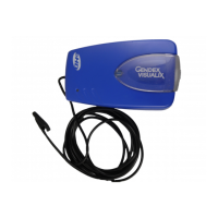
Step 4: Connect the device end of the USB 2.0
cable to the USB 2.0 connector on the back of
the DenOptix QST scanner. Connect the
scanner to a grounded power outlet. Make
sure the other end of the USB 2.0 cable is
connected to the USB 2.0 port on the
computer.
Step 5: Connect the computer to a network if
desired. Refer to your Imaging Software User
Manual and Installation Guide for more
information on how to configure the Imaging
Software in a network.
Step 6: Turn the power on the scanner. The
green light on the scanner should be lit at this time. If it is not, follow the trouble shooting
guidelines on page 5-6.
Step 7: After the Windows operating system is loaded, a message indicating that a “New
Hardware” has been found will appear. Follow the on-screen instructions to finalize the
installation.
Network Installation
Refer to your network/computer professional for network installation, configuration and
maintenance. Refer to your Imaging Software User Manual and Installation Guide for more
information on how to configure the Imaging Software in a network.
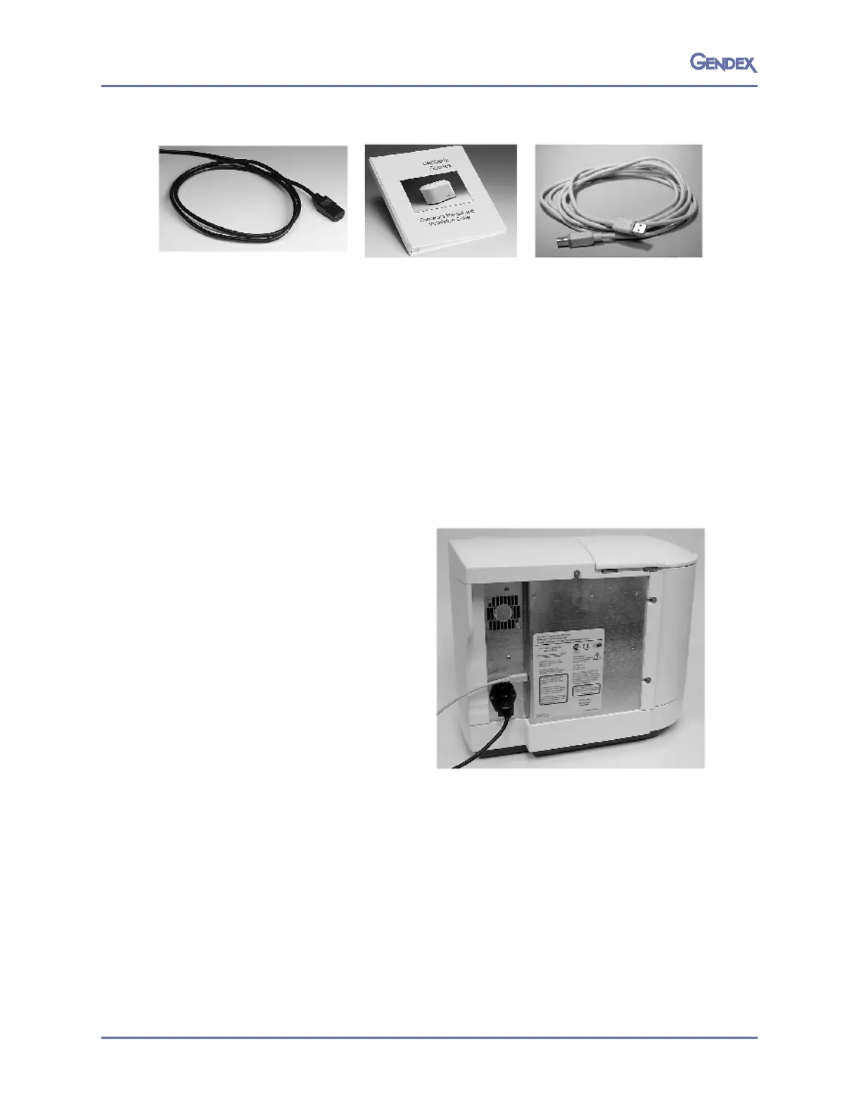
Power Cord, 1each
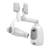
User Manual and Installation
Guide (Software and
Hardware), 1 each
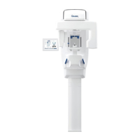
USB 2.0 cable (6 ft, 2 m)
1 each