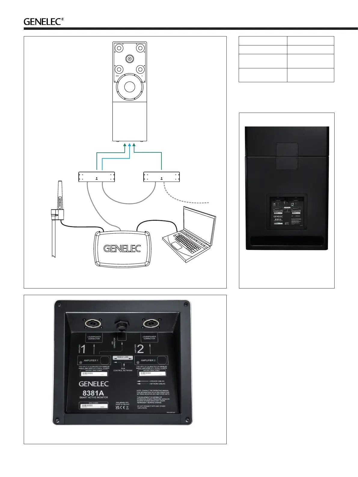
Figure 6. GLM control network cabling, speaker cables and LED connecting cable
POSITION
MICROPHONE
GLM
NETWORK
RAM81
LINK
GLM
NETWORK
USB
RAM81
AMPLIFIER 1
RAM81
AMPLIFIER 2
SPEAKER CABLE TO
LOUDSPEAKER
CONNECTOR 2
LED CONNECTION
CABLE
SPEAKER CABLE TO
LOUDSPEAKER
CONNECTOR 1
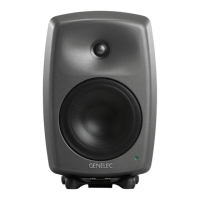
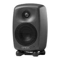
Figure 7. Connector panel on the bottom enclosure
Do not exceed 1 Nm (0.7 ft lb) torque.
Now 8381A enclosure is ready for
attaching the cabling to the amplier system.
Amplifier to Enclosure Cable Assembly
The cable assembly is designed to go
between the two ampliers and the bottom
monitor enclosure. Each amplier is marked
next to the loudspeaker connector. The
amplier marked as '1' must be connected to
the enclosure input 1 and amplier marked as
'2' must be connected to enclosure input 2.
The cables also indicate the markings ‘1’
and ‘2’. Match the markings in the cables
to the marking on the amplifier and the
enclosure input terminal.
If you need a custom cable length
between the ampliers and the enclosure,
please contact Genelec for availability of
custom cable assemblies.
Table 1. Recommended minimum cable
gauges fot dierent speaker cable lengths
Cable gauge Max. cable length
2.0 mm
2
(14 AWG) Up to 10 m (100 ft)
3.3 mm
2
(12 AWG) 30 - 40 m
(100-130 ft)
5.3 mm
2
(10 AWG) 40 - 60 m
(130 - 200 ft)
Figure 8. Back panel pf the 8381A with
enclosure to enclosure cables and
covering plates installed