heavy, more than 70 kg (155 lb).
The top enclosure DCW area is covered
by a plastic protection sheet. Do not remove
this until the enclosure is fully assembled in
its intended location and do not apply any
pressure on it as this may damage the 5 in
midrange domes. Remove the protection
sheet attaching tapes carefully to avoid
marks in the paintwork. Store the protective
sheet for possible later use if the top
enclosure has to be moved.
Note: The top enclosure must be placed
on top of the bottom enclosure to get the
designed acoustic characteristics and
frequency response quality. Genelec does
not recommend the top enclosure to be
placed away from the bottom enclosure and
does not support such placements.
Warning: Do not apply pressure on the 5
in domes in the DCW area. Avoid touching
the domes. Structural changes in the domes
may aect the sound quality.
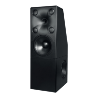
Placement and Aiming
The 8381A monitor is designed to be placed
free-standing on the oor. The monitor has
point source characteristics down to 200 Hz.
Because of this the listening distance can
be chosen quite freely – down to a listening
distance of around 1 m (3 ft). The automatic
calibration system with the adaptive woofer
system allows excellent performance in free-
standing positions, away from room walls.
These characteristics together allow the
monitor to be placed at the ideal loudspeaker
locations for monitoring in the room.
Acoustic Axis Definition
The monitor acoustic axis is at the centre of
the coaxial driver. This axis from the middle
of the coaxial driver should point at the
listener. This is also the measuring axis of
the system (see Figure 4).
Selecting the Installation Height
Consider the need of lifting up the 8381A if
you have high furniture such as the mixing
console, to give the mid and high frequency
drivers enough clearance over the tops of
the furniture. An optional 0.3 m (1 ft) pedestal
is available from Genelec for this.
Aiming the Acoustic Axis
The monitor should be aimed horizontally
and vertically toward the listener.
When the monitor is placed on the
floor, the acoustic axis height is 1.2 m.
When listening at the typical sitting height
(1.2 m), no vertical alignment is needed.
In applications where the monitoring is
frequently done standing up, axis direction
should be adjusted vertically to midway
between the standing and seated positions,
typically 1.5 m (5 ft from the oor), allowing
similar frequency response for standing and
seated listening positions.
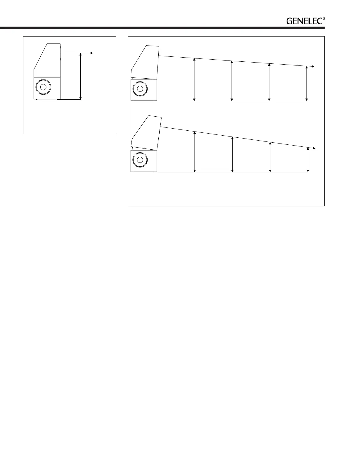
Acoustic Axis Optimisation When
Monitor is Lifted
When the monitor is lifted on a pedestal,
the top enclosure can be tilted towards the
listener. For a typical seating height, this
normally means the top enclosure acoustic
axis is pointing slightly down. This can be
achieved by tilting the top enclosure slightly
forward using an incliner wedge, to achieve
either a 4 or 8 degree tilt-down angle. These
wedges are included with the 8381A. The
wedges are marked with the tilt angle.
Genelec does not recommend using any
other method for tilting the top enclosure as
the wedges are designed to create structural
rigidity and ensure that the enclosure stack
has maximum stability when tilted.
See Figure 5 for the acoustic axis height
at different distaces when using the tilt
wedges.
Connections
Enclosure to Enclosure Cabling
Locate the covering plates at the top of the
bottom enclosure and the bottom of the
top enclosure – these are included in the
Accessories Kit.
Locate and connect the 0.25 m (0.8 ft)
at cable and 0.25 m (0.8 ft) RJ45 cables
between the top and bottom enclosures.
These cables are provided in the Accessories
Kit.
After cables are in place, attach the
covering plates using the included screws.
1208 mm
(47 9/16 in)
Acoustical axis
Figure 4. Height of the acoustical
axis. Horizontally the axis is located
at the centreline of the enclosure
Acoustical axis
1140 mm
(44 7/8 in)
1071 mm
(42 1/8 in)
1001 mm
(39 3/8 in)
931 mm
(36 5/8 in)
1000 mm
(39 3/8 in)
2000 mm
(78 3/4 in)
3000 mm
(118 1/8 in)
4000 mm
(157 1/2 in)
Acoustical axis
1074 mm
(42 5/16 in)
934 mm
(36 3/4 in)
793 mm
(31 1/4 in)
652 mm
(25 11/16 in)
1000 mm
(39 3/8 in)
2000 mm
(78 3/4 in)
3000 mm
(118 1/8 in)
4000 mm
(157 1/2 in)
Figure 5. Height of the acoustical axis using the 4 deg (above) and 8 deg (below)
incliner wedges. Do not use the wedges to tilt the top enclosure upwards
 Loading...