You may also build your own
interconnecting cable assembly. For this,
connect the eight-pin 'Speakon' connectors
pin-to-pin using at least the cable gauge
given in Table 1. The cable gauge depends
on the length of the cable. Pin-to-pin
connection means that pin number 1 in the
rst Speakon connector is connected to pin
number 1 in the second Speakon connector,
and so on.
As the RAM-81 ampliers can produce
potentially hazardous voltages, use a
trained electrical technician to build and
connect the custom Speakon cables to
ensure safety and compliance with local
regulations.
Standard CAT 5 or CAT 6 cables can
be used for the RJ-45 interconnection
between the ampliers and the enclosure,
and dierent lengths are available in stores
selling CAT cables. Do not use special CAT
cables with crossed interconnections or
cables that do not have all pins connected.
RAM-81 LINK Amplifier Communication
Cable
The two ampliers communicate using one
interconnecting control network cable. This
link interface is named 'RAM-81 LINK'. This
cable is provided.
The GLM network cable is connected to
Amplier Unit 1 and, if needed, continued
to further Genelec SAM monitors using the
GLM output on Amplier Unit 2. See Figure
6.
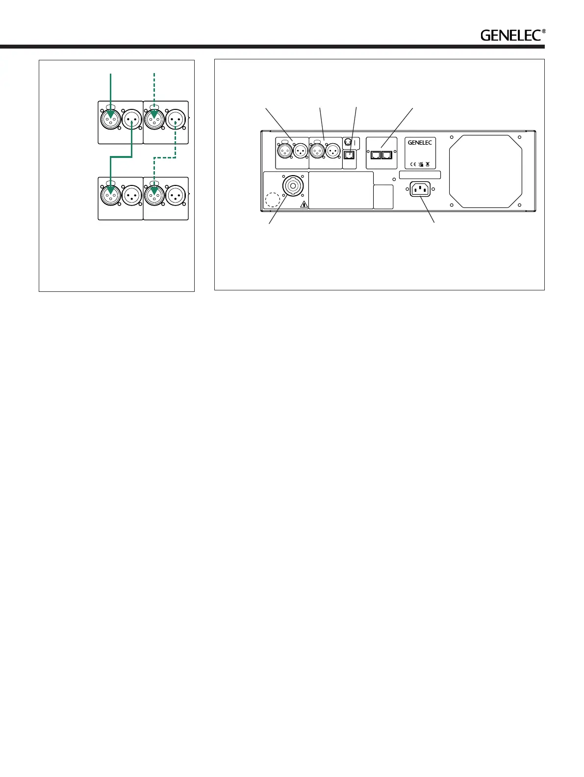
Audio Cabling
The incoming audio signal(s) are connected
to Amplifier Unit 1. The THRU out is
connected to the input of Amplier Unit 2.
XLR male-to-female cables are provided for
this. See Figure 9.
System Calibration
GLM software can fully set up your Genelec
Smart Active (SAM) Monitoring system.
GLM software works with SAM monitors to
minimise the unwanted acoustic inuences
of the monitoring room and helps your mixes
sound great, everywhere. Among other new
features, GLM system calibration includes
the optional GRADE Report, extending
GLM's scope beyond ultra-precise system
calibration, to complete in-depth room and
system acoustical analysis.
Connecting GLM Network
In order to use the setup software, the GLM
Network must be connected (see Figure 6):
• Link Amplier 1 and Amplier 2 using the
supplied CAT5 (RJ45) cable. Connect
the cable between the RAM-81 LINK
connectors on both ampliers.
• Link all monitors and subwoofers in
a daisy-chain manner by connecting
CAT5 (RJ45) cables to the 'CONTROL
NETWORK' connectors of all the
Genelec SAM monitors and RAM
ampliers. The order connection in the
daisy-chain is not important.
• Run the nal network cable to GLM
network input in the GLM Adapter
device.
• Connect the GLM Adapter device to the
USB connector on your computer.
Measurement Microphone Placement
Place the Genelec measurement microphone
on a stand at the listening location of the
engineer, with the microphone pointing
upwards and the microphone top at the
height of the engineer’s ear at the position
where the engineer would normally work.
The microphone is a part of the GLM User
Kit. Run the microphone cable into the
microphone input of the GLM Adapter
device.
In case of a multi-point calibration, several
microphone positions are used. Consult
the GLM Operating Manual for further
instructions.
Installing and Using GLM Software
Download GLM software at the Genelec
web site (www.genelec.com). Install the
GLM software. The software comes with an
operating manual explaining the process of
calibrating the monitoring system. Follow
the GLM software instructions to measure
and set up your monitors. You can choose
to calibrate for one listening position or
for a wider listening area, using multiple
measurement microphone positions.
GLM software can calibrate any SAM
monitoring system up to tens of monitors
ANALOG
IN
DIGITALIN
AES/EBU
DIGITALTHRU
AES/EBU
ANALOG
THRU
ANALOG
IN
DIGITALIN
AES/EBU
DIGITALTHRU
AES/EBU
ANALOG
THRU
ANALOGUE
SIGNAL
DIGITAL
SIGNAL
AMPLIFIER 1
2
Figure 9. Connecting audio input using
analogue audio (solid line) or alterna-
tively using AES/EBU audio (dashed)
inputs and thru outs
Figure 10. RAM-81 amplier connector panel. Amplier 1 shown, amplier 2 has
similar layout. However, the ampliers are not interchangeable
ANALOG
IN
DIGITALIN
AES/EBU
DIGITALTHRU
AES/EBU
ANALOG
THRU
RAM81 AMPLIFIER
MODULE
www.genelec.com
MADE IN FINLAND
This device complies
with FCC Part 15 and
Canadian ICES003
radio frequency Class
B emission
requirements. Refer
to operating manual
for full information.
MAINSINPUT
50 /60Hz1100 W
100 240 V~
SERIAL NUMBER
LED
CONNECTOR
LOUDSPEAKER
CONNECTOR
WARNING ELECTRIC SHOCK HAZARD. DO NOT OPEN. DO NOT SUBJECT TO
WATER OR MOISTURE. NO USER SERVICEABLE PA RTS INSIDE. REFER
SERVICING TO QUALIFIED PERSONNEL. USE EARTHED MAINS CONNECTION
ONLY.
AVERTISSEMENT RISQUE DE CHOC ÉLECTRIQUE. NE PAS OUVRIR. NE PA S
EXPOSER À L'EAU OU L'HUMIDITÉ. AUCUN COMPOSANT À L'INTÉRIEUR
REMPLAÇABLE PA R L'UTILISATEUR. ADRESSER TOUTE RÉPARATION À UN
PERSONNEL QUALIFIÉ. CET APPAREIL DOIT ÊTRE RACCORDÉÀLA TERRE.
LAITE ON LIITETTÄVÄ SUOJAKOSKETTIMILLA VARUSTETTUUN PISTORASIAAN.
APPARATETMÅ TILKOPLES JORDET STIKKONTAKT.
APPARATENSKALL ANSLUTAS TILL JORDAT UTTAG.
APPARATETSSTIKPROP SKAL TILSLUTTES EN STIKKONTAKT MED JORD SOM
GIVER FORBINDELSE TIL STIKPROPPENS JORD.
THIS AMPLIFIER HAS BEEN CALIBRATED FOR USE WITH THE LOUDSPEAKER
INPUT MARKED WITH THE SAME SERIAL NUMBER. DO NOT MIX THE
CALIBRATEDAMPLIFIER/LOUDSPEAKER PAIRS! TURN OFF POWER BEFORE
DISCONNECTING LOUDSPEAKER CONNECTIONS!
NOTE!
213
THRU
IN
1
1
23
3
2
GND
+
RAM81
LINK
GLM
CONNECT TO
INPUT
CONTROL NETWORK
1
AND
THRU
ORS
DIGITAL IN AND
DIGITAL THRU
CONNECTORS
LED
CONNECTOR
RAM-81 LINK AND
GLM CONNECTORS
LOUDSPEAKER
CONNECTOR
MAINS
CONNECTOR
 Loading...