Operation
Integrated Load Center Owner’s Manual 19
Transfer Switch Settings #3
This is the third screen of the transfer switch settings
screens. The second screen can be accessed by
pressing the left arrow button. To return to the system
configuration menu screen press the return arrow
(Figure 4-9).
Engine Warm Up Timer - Press the screen button that is
displaying the current value to set this value. Enter the
warm up time in seconds using the pop-up box. The
acceptable range is shown on the screen. Press ENTER
to change setting.
Engine Cool Down Timer - To set this value, press the
screen button that is displaying the current value. Using
the pop-up box, enter the engine cool down time in
minutes. The acceptable range is shown on the screen.
Press ENTER to change setting.
Minimum Run Timer - To set this value, press the
screen button that is displaying the current value. Using
the pop-up box, enter the minimum run time in minutes.
The acceptable range is shown on the screen. Press
ENTER to change setting.
Figure 4-9. Transfer Switch Settings #3
Transfer Switch Settings #4
This is the fourth screen of the Transfer Switch settings
screens. The third screen can be accessed by pressing
the left arrow button. To return to the system
configuration menu screen press the return arrow
(Figure 4-10).
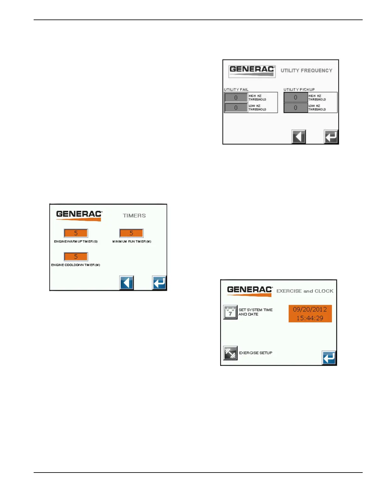
Utility Fail Frequency Settings (Hz):
•High Frequency Threshold – A utility frequency
above this setting will cause a transfer to standby
source.
•Low Frequency Threshold – A utility frequency
below this setting will cause a transfer to standby
source.
Utility Pickup Frequency Settings (Hz):
•High Frequency Threshold (Utility High Fail
Frequency Setting +/- 1Hz) – A utility frequency
above this setting will inhibit transfer to utility
source.
Low Frequency Threshold (Utility Low Fail
Frequency Setting +/- 1Hz) – A utility frequency below
this setting will inhibit transfer to utility source.
Figure 4-10. Transfer Switch Settings #4
Exercise and Clock Setup
This is the screen to set the system clock and exercise
functions (Figure 4-11). To return to the system
configuration menu screen press the return arrow.
System Time and Date - The time is displayed in a 24
hour format. To set the system clock, press the screen
button next to the text. Using the pop-up box, highlight
the setting to be changed with the left and right arrows.
Use the “+” and “-“ buttons to change the setting. Press
ENTER to update the setting (Figure 4-11).
Exercise Setup - To setup the exercise function, press
the screen button next to the text. This will bring up the
exercise setup screen on the next screen.
Figure 4-11. Exercise and Clock Setup