Modbus Map
Integrated Load Center Owner’s Manual 27
Section 6: Modbus Map
Description
This document describes the transfer switch data
available via the secondary communication port on the
touch screen.
Communication Settings
Modbus Settings
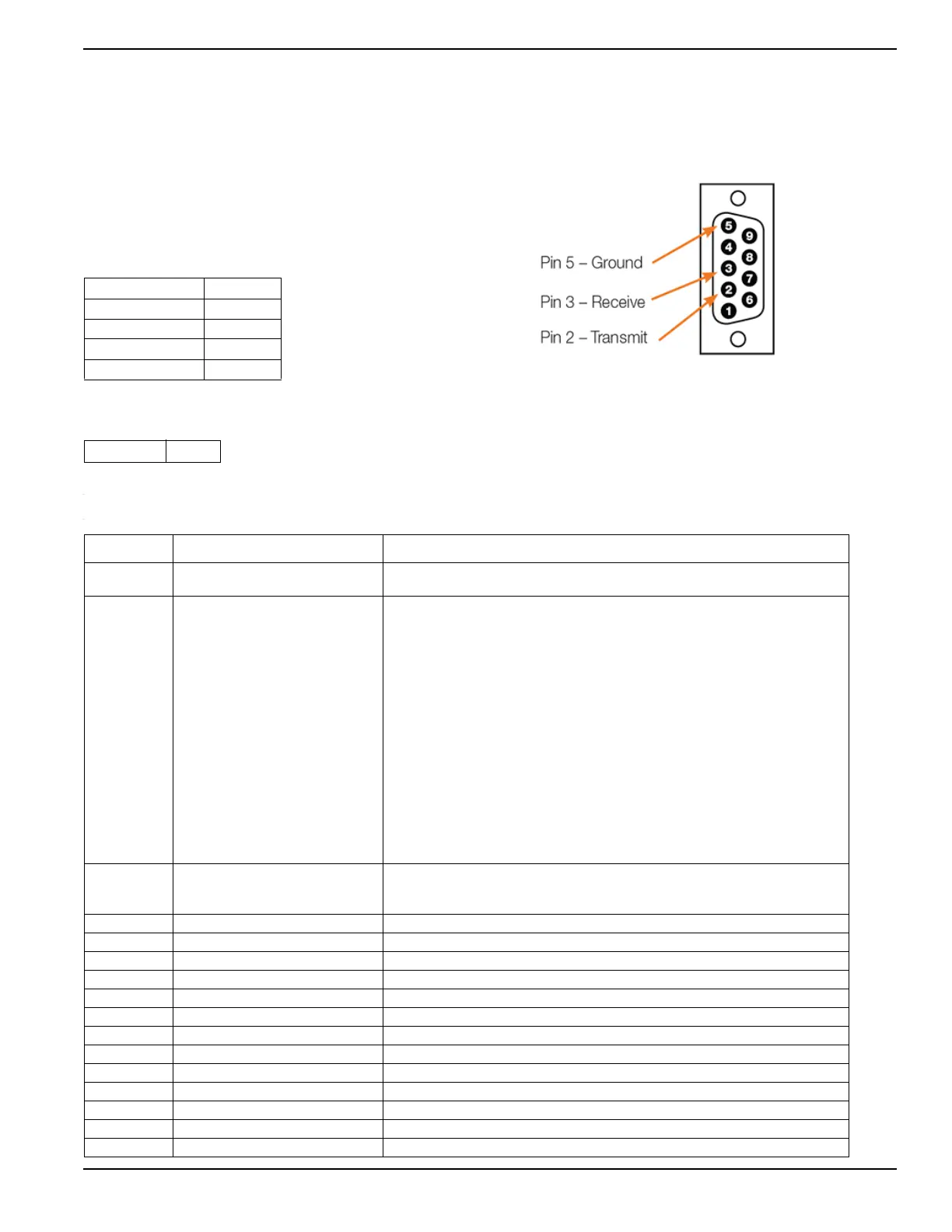
RS232 Pinout
Data Map
Protocol RS-232
Baud rate 9600
Data bits 8
Parity None
Stop bits 1
Station 157
Register Data Notes
500 [0:15]
Bit 6: Automatic Mode
Bitmap
501 [0:15]
Bit 0: Util ok
Bit 1: Util loss delay
Bit 2: Gen starting
Bit 3: Gen ok
Bit 4: Synching
Bit 5: TDN
Bit 6: On generator
Bit 7: Util recover delay
Bit 8: Gen minimum run
Bit 9: Gen cooldown
Bit 10: Gen stop
Bit 11: Exercising
Bit 12: System fault
Bit 13: Transfer to gen
Bit 14: Transfer to util
Bit 15: Warmup
Bitmap
502 [0:15]
Bit 1: In test mode
Bit 2: In fast test mode
Bitmap
503 Measured Va AB line-to-line (AN for single phase)
504 Measured Vb BC line-to-line (BN for single phase)
505 Measured Vc CA line-to-line (unused for single phase)
506 Measured Ia
507 Measured Ib
508 Measured Ic Unused for single phase
509 Utility Volts Average
510 Utility Current Average
511 Utility Frequency Average, x100
512 Utility Power Factor x100
513 Utility kW Average
514 Generator Volts Average
515 Generator Frequency Average