8
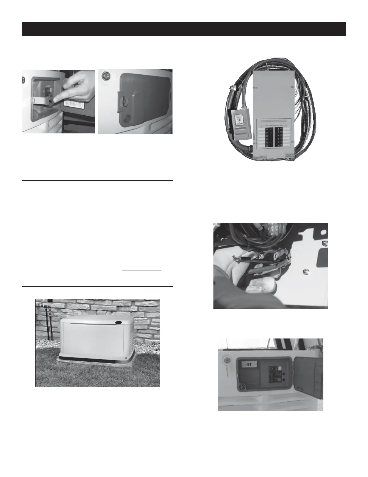
4. Replace the protective cover plate and retaining screw, and
lock the connection box.
5. For 10-20 kW models, locate the metal hasp that is packaged
in the owner’s manual bag. Insert the hasp in the slot located
on the left side of the external circuit breaker box. Be sure that
the clip of the hasp is facing toward the front of the generator.
If desired, lock the external box.
GENERATOR ACTIVATION
When battery power is applied to the generator during the
installation process, the controller will light up. However, the
generator still needs to be activated before it will automatically run
in the event of a power outage.
Activating the generator is a simple one time process that is
guided by the controller screen prompts. Once the product is
activated, the controller screen will not prompt you again, even if
you disconnect the generator battery.
After obtaining your activation code, please complete the following
steps at the generator’s control panel in the Activation Chart
(shown on the following page).
GENERATOR CONNECTIONS – EZ SWITCH
1. If the generator comes with an external connection box and
5’ seal-tite whip pre-wired and connected to the generator, no
additional connections are necessary at the generator. Skip
the following section and proceed with Appendix A, EZ Switch
Installation & Operational Testing.
2. If the EZ Switch was purchased separately from the generator,
the 5’ seal-tite whip will need to be connected to the
generator. To complete the wiring, run the ¾” conduit for the
power leads and control wires from the external connection
box to the generator.
3. Remove the two screws securing the connection area cover,
and remove the cover.
4. Feed the wires through the back of the generator and secure
the conduit with the lock nut.
5. Run the power leads through the strain relief provided.
6. The circuit breaker is attached to the exterior access panel.
General Information
 Loading...


