17
3. The grounding that is normally in the main panel must be
accomplished in the service rated switch and must be
disconnected in the existing distribution panel. Refer to the
National Electrical Code (NEC) for complete information on
grounding and bonding.
ELECTRICAL CONNECTIONS
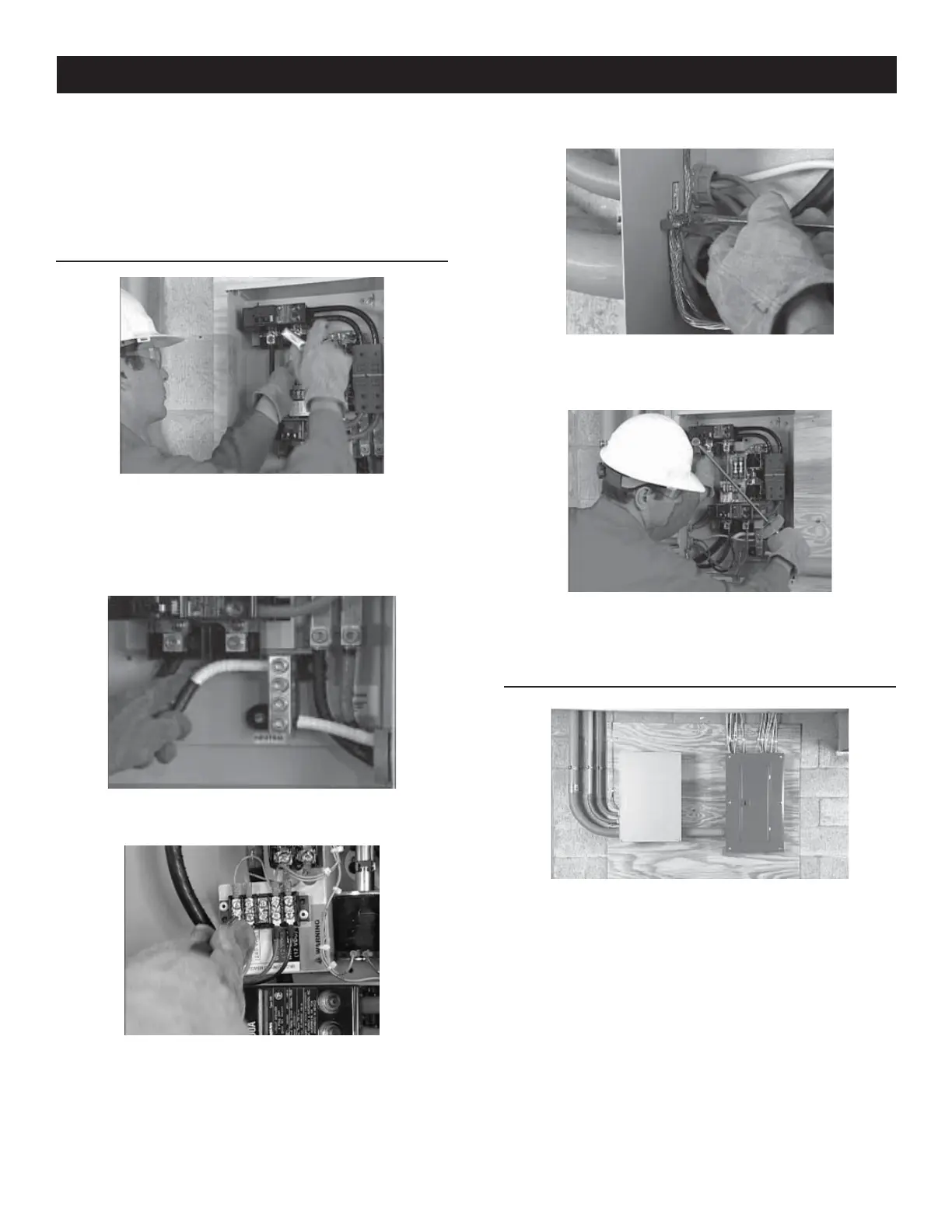
1. Connect the power leads from both the generator and the
utility to the appropriate lugs in the transfer switch. The lugs
are clearly marked in the switch.
N = Normal Utility Supply
E = Generator Connection Panel
T = Load Distribution Panel
2. Neutral wires from both the utility and the generator are
connected to the same neutral lug in the switch.
3.
Connect the control wires from the generator to the designated
locations. Wires 0, 23 and 194 connect to the terminal strip; N1,
N2, and T1 connect directly to the fuse holders.
4. Complete the transfer switch wiring by connecting the
equipment ground wires from both the utility and the
generator to the ground lug.
5. Being careful to support the lugs, torque the lugs in the
transfer switch to the specifications shown on the transfer
switch. Decal located on the inside of the switch door.
OPERATIONAL TESTING
1. If installing the RTSD switch, the service was changed so make
sure the terminations are good before re-energizing the utility.
Appendix B
 Loading...


