20
NOTE:
Even if the generator is running smoothly at
this point, a drop in gas pressure indicates that
the supply is barely adequate to supply the
generator’s needs. Changes in the generator load,
or additional gas demand by other appliances
may affect the generator’s performance. Verify
gas pressure and pipe sizing. Unhook the
manometer and reinstall the port plug.
17. Switch the utility breaker ON to restore utility power to the
home.
18. The generator will continue to run to allow the engine to cool
down, then shut itself off.
19. Shut OFF utility power again. The generator should start and
the entire priority load should transfer to the generator.
20. Close the main breaker to restore utility power and allow the
engine to cool down and shut itself off.
Operational tests are now complete. Refer to Appendix E
– Setting the Automatic Exercise Function to complete the
installation.
APPENDIX C – DIGITAL LOAD MANAGEMENT
(DLM)
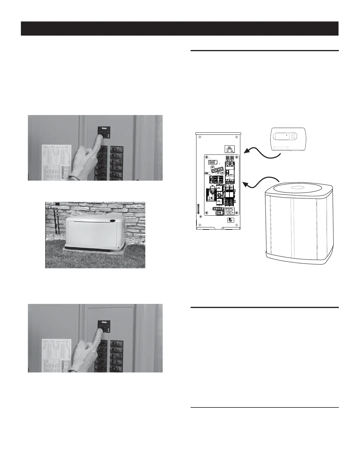
1. To control an Air Conditioner, connect the Y terminal of the
thermostat to one of the A/C 1 terminals. Connect the other
A/C 1 terminal to the Y terminal on the air conditioner.
Use 18 – 26 AWG copper wire. Refer to the Owner’s Manual
for specific torque/connection requirements.
2. To control a second air conditioner repeat the above using
terminals marked A/C 2.
65
NOTE:
For specific AC control wire information, please refer to the
HVAC systems Owner’s/Operation Manual.
APPENDIX D – DIGITAL LOAD MANAGEMENT
(DLM) MODULES
The load controller can operate up to four separate DLM’s, each
one connected the same way as below.
• The NEMA 3R Enclosure of the DLM module can be installed
indoors or outdoors. If mounting outdoors the enclosure MUST
be orientated with the drain hole at the bottom.
• The DLM module is fitted with conduit knockout locations.
These knockout locations are the only locations that conduit
should be attached to the enclosure. A grounding stud is
provided inside the enclosure in order to ground the conduit.
CONNECTING LOAD SHED MODULE (LSM) CONNECTIONS
The LSM can control an air conditioner (24 Vac) directly or
a separate contactor (120 Vac) which can control any load
connected to it (see Figure).
Appendix C
 Loading...


